The Ultimate Guide to Coil Wrapping Machine
Coil wrapping machines are primarily divided into two categories: vertical coil wrapping machines and horizontal coil wrapping machines.
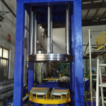
The vertical coil wrapping machine is designed for eye to wall coil wrapping. There are different version to pack the coil from small to big. The loading way is by manually and crane that depends on the weight and shape of coil.
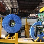
On the other hand, the horizontal coil wrapping machine is meant for horizontally positioned coils with eye to sky. This machine efficiently wraps coils using materials such as stretch film, providing enhanced protection during handling and transportation.
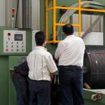
1. SEMIAUTOM COIL WRAPPING MACHINE
Key Components:
- Frame (1): The main structure that holds the entire machine.
- Driven Wheels (2): These wheels, arranged in a circular pattern, help rotate the coiling ring.
- Coiling Ring (3): A circular ring with an adjustable opening where the steel coil passes through. It spins to wrap the coil.
- Support Wheels (4): Located on the sides of the coiling ring, these wheels provide extra support and stability.
- Grooves and Protrusions (5, 6, 7): These are specifically designed grooves and protrusions that fit together tightly, ensuring smooth rotation between the driven wheels and the coiling ring.
- Motors (8, 9): These power the driven wheels and the system that adjusts the height of the coiling ring.
- Support Ring (10): A stationary ring that helps guide the driven wheels.
- Support Pillar (11): A vertical post that holds the second motor and helps support the structure.
- Main Rod (12) and Driven Rod (13): These rods are connected to the motor and allow the coiling ring to move up or down to accommodate different coil sizes.
- Clamp (14): This holds the support ring in place and can be adjusted for flexibility.
- Support Columns (15, 16, 17): Vertical columns that support the coil and ensure it stays in position.
- Rollers (18): Positioned between the support columns, they keep the steel coil steady during wrapping.
How the Machine Works:
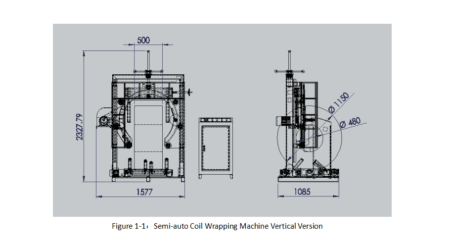
Basic Structure:
The machine figure 1-1 semiautom coil wrapping machine vertical version has a sturdy frame with several driven wheels arranged in a circle. rapping ring sits on these wheels, through which the rotating steel coil wrapped by the packing material . The opening in the ring can be adjusted based on the size of the coil.
Support and Movement:
Support wheels with grooves hold the ring in place during wrapping. The driven wheels are powered by a motor, causing them to rotate the ring with speed adjustment. The smooth runing ring carries the packing material for coil eye through packing. Thanks to the grooves and protrusions that the ring and driven wheels fit together tightly. And the wheels position adjustable for friction adjustment.
Height Adjustment:
The machine is equipped with a lifting mechanism that adjusts the height of the wrapping ring per different coil OD. A second motor, mounted on the support pillar, controls the height by moving the main board and driven rods through a gear system. This ensures that the coiling ring adjusts to the coil’s size, allowing for safety and precise wrapping.
Coil Support:
The steel coil is supported by a base with one top support roller and two base supportive rollers. The supportive roller extend downward to match the width of the coil. It is for suporting and holding the coil steady during the wrapping process.
Efficient Wrapping:
The entire machine is designed to wrap steel coils quickly and tightly, ensuring the coil is securely packed and protected from moisture and dust.
2. SEMIAUTO HORIZONTAL COIL WRAPPING MACHINE

The coil wrapping machine figrue 2-1:semiauto horizontal coil wrapping machine effectively holds the coil package between powered rollers and pressure rollers. The powered rollers rotate the coil while the open rotating ring wraps it with tape. This design prevents the coil package from deforming or wobbling during the wrapping process, ensuring an even and tightly wrapped coil.
A coil wrapping machine consists of the following components:
- Frame (1):The main structure that supports the entire machine.
- Open Rotating Ring (2): Mounted on the frame, this ring rotates to wrap the coil with tape.
- Material Holder(3): Attached to the rotating ring, it holds the wrapping tape.
- Support Wheels(4-6): The outer edge of the rotating ring touches a set of rotating support wheels that guide the ring during the wrapping process.
- Powered Rollers (7): Positioned on both sides of the rotating ring, these rollers help rotate the coil and are connected to a driving mechanism.
- Pressure Rollers(8): Located above each powered roller, they are movable and press down on the coil to keep it steady during wrapping. These rollers are also connected to the frame.
- Cylinder (9): For pressing and holding the coil for wrapping
- Motor (10):Driving for coil turning and ring turning.
In detail:
- The driving mechanism includes a motor mounted on the frame, which powers the rollers using a timing belt.
- The pressure rollers are connected to the frame using cylinders, allowing them to be adjusted as needed.
Detailed Description:
Figures 1 and 2 illustrate the structure of the coil wrapping machine:
- The machine includes a frame (1), an open rotating ring (2), and a Material Holder (3) for the wrapping tape.
- The support wheels (4, 6) guide the rotating ring and are driven by a motor (5) connected through a timing belt. The motor powers the support wheels, which cause the rotating ring to spin.
- On each side of the rotating ring are powered rollers (7), connected to the frame. These rollers are powered by a motor (10) through a timing belt, enabling them to rotate the coil.
- Pressure rollers (8) are located above the powered rollers and are connected to the frame via cylinders (9). The cylinders are used to lower the pressure rollers, clamping the coil securely between the powered and pressure rollers.
- A PLC (Programmable Logic Controller) controls both the motors and cylinders, ensuring precise operation.
Wrapping Process:
1.The coil or tire is suspended between the powered rollers.
2.The cylinders lower the pressure rollers to secure the item between the powered and pressure rollers.
3.The PLC adjusts the pressure to ensure a firm hold.
4.The wrapping tape is fixed to the item, and the open rotating ring begins to spin while the powered rollers rotate the coil.
5.This process results in an even and tight wrap around the coil.
This design ensures that the coil or tire is wrapped efficiently, with consistent pressure, and without deformation or wobbling during the process.
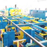
3. VERTICAL COIL WRAPPER WITH TROLLEY

Technical Field:
This model is a coil wrapping machine figure 3-1:coil wrapping machine with trolley with a trolley system, specifically designed to wrap heavy metal coil products, like steel coil, wire coil and copper coils. The trolley creats the opereation space for coil loading & unloding from top size to avoid the inpecting wrapping station
The machine is built around the following components:
- Gantry Frame (1): The main structure of the machine.
- Moving Rails (2): Positioned at the base of the gantry to guide the mobile carriage.
- Wrapping Device (3): The ring device Mounted on the lifting system, responsible for wrapping the coils.
- Lifting Device (4): Moves the wrapping device up and down to adjust to the height of the coil.
- Trolley Carriage (5): Moves along the rails with motor gear driving, carrying the coils into the wrapping station. Sensor for positioning
- Carriage Drive System (6): Powers the movement of the mobile carriage.
- Supportive Roller (7) and Supportive Roller (8): It is the driving device for coil 360 degree rotating. These are located on either side of the trolly carriage to support and rotate the coil during wrapping.
- Power Wheel (9): Positioned under the trolley carriage that drived by motor for trolly movement.
- Ring driving wheels (10): It is the power trismit device for ring rotating that drived by the motor at the behind of the wrapping station.
- Shield (11) : for safety guiding the ring and packing material
- Side Rollers (12) for coil holding and protecting.
Implementation:
The gantry frame is made of sturdy channel steel, providing the main support for the entire machine. The lifting device is mounted on vertical supports on the gantry. A set of powered sprockets on the crossbeam drive the chains, allowing the wrapping device to move up and down, adjusting to the center height of the coil for precise wrapping.
The moving rails , installed at the base of the gantry, guide the movement of the trolley carriage. The carriage drive system , positioned at the center of the mobile carriage, powers its movement along the rails. The left and right Suppotive roller and are located at opposite ends of the mobile carriage, each powered by its own motor. On either side of these assemblies, side rollers are installed to prevent the wrapped product from shifting laterally and to adjust the width of the items being wrapped.
Wrapping Process:
Step 1: Loading the coil The first coil (A) is lifted by a crane and placed on one of the power roller assemblies.The ring height level adjusting for coil OD and supportive roller shrink for hold the coil
Step 2: The trolley carriage then moves into the wrapping position. Once in place, the power rollers start rotating the coil while the wrapping device begins to wrap it with material.
Step 3: Automatic packing material length checking and cutting per coil size that setting in the HMI.
Step 4: Loading the second itemWhile the first coil is being wrapped, the second coil (B) is placed onto the other power roller assembly, preparing it for the next wrapping cycle.
Step 5: Continuous wrapping After the first coil is wrapped and moved out of the station, the second coil automatically moves into position for wrapping. Simultaneously, a third coil can be loaded onto the waiting power roller assembly. This continuous, automated process ensures high efficiency and seamless transitions between wrapping cycles.
The entire machine is controlled by an automated computer system. Photoelectric sensors are used to position the coils accurately and ensure smooth operation throughout the wrapping process. This system allows for precise, error-free wrapping while minimizing manual intervention.
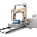
4. AUTOMATIC HORIZONTAL STRETCH WRAPPER
The automatic film feeding and cutting device in coil wrapping machines offers a specialized solution for efficiently wrapping circular products like steel and copper coils online.
By integrating features such as a rotating ring, automatic feeding arm, and cutting mechanism, the device streamlines the wrapping process. It eliminates the need for manual feeding and cutting of the wrapping material, allowing for continuous, automated packaging.
This design not only enhances production speed but also ensures precise and consistent wrapping, making it ideal for high-volume industrial on-line applications that demand reliability and efficiency.
In the Figures:

1.Main Board 2. Guiding Wheel Assembly 3. Automatic Cutting Mechanism 4. Automatic Band Feeding Arm 5. Open Rotating Ring 6. Material Feeding Unit 7. Conveying Wheels 8. Rotary Drive Unit 9. Connecting Rod 10. Front Bearing Seat 11. Rear Bearing Seat 12. First Sleeve 13. Second Sleeve 14. First Connecting Block 15. Second Connecting Block
Key Components:
As shown in Figure 4-1:automatic horizontal stretch wrapper, a preferred implementation of the automatic band feeding and cutting device for a wrapping machine includes the following components:
The material feeding unit is mounted on one side of the main board to provide the wrapping tape. On the opposite side, there is a material passage opening. The guiding wheel assembly is attached to the main board, while the open rotating ring is mounted on the other side. This ring has an open structure, with its inner side lined up with the material passage opening. Around the ring, several conveying wheels are arranged to assist the process.
The guiding wheel assembly is positioned between the material feeding unit and the rotating ring, allowing the wrapping tape to move through smoothly.The automatic cutting mechanism is located at the bottom of the main board and is responsible for cutting the wrapping tape. The automatic band feeding arm is installed at the top of the main board and rotates to guide the wrapping tape into the open rotating ring.
Wrapping Process:

1. First, the product is moved into position by the rotary support mechanism. The wrapping tape is fed from the material feeding unit and guided through the guiding wheel assembly. The automatic cutting mechanism holds the end of the tape.
2. After the system starts, and the rotating cylinder moves the connecting rod, causing the automatic band feeding arm to rotate. The swing arm, driven by the swing cylinder, guides the tape into the open rotating ring.
3. The rotating ring begins to turn slowly, powered by the friction drive wheels. The ring passes through the product, and the tape starts to wrap around the outer side of the conveying wheels.
4. As the rotating ring continues to turn, the tape is pulled to the inside of the product by the conveying wheels. The swing arm moves outward, creating a gap from the conveying wheels.
5. Once two or three layers of tape are tightly wrapped around the product, the clamping cylinder separates the movable clamping plate from the fixed clamping plate, releasing the tape from the automatic band feeding arm.
6. Finally, the rotating ring speeds up, and the excess tape is stored on the conveying wheels. When the correct amount of tape is used, the remaining tape on the wheels completes the wrapping. The automatic band feeding arm returns to its starting position, and the rotating ring stops. The clamping cylinder resets to hold the tape, and the automatic cutting mechanism cuts the tape.
Key Features:
1.Material Supply Mechanism: Supplies the wrapping material to the machine.
2.Rotating Ring: Rotates around the product to wrap it.
3.Cutting Mechanism: Cuts the material automatically once the wrapping is complete.
4.Band Feeding Arm: Moves the wrapping material into position for the next cycle.
Preferred Setup:
- The cutting mechanism uses pneumatic shears for fast and precise cutting.
- The feeding arm consists of a rotating drive, support bearings, and cylinders that enable smooth rotation and feeding of the wrapping material into the correct position.
Advantages:
- Increased Efficiency: The automation of both feeding and cutting greatly reduces manual intervention, making the process faster and safer.
- Better Quality Control: With automated processes, the wrapping is more consistent, ensuring better packaging quality.
- Labor Savings: This system eliminates the need for manual feeding and cutting, saving labor costs and improving safety by reducing human involvement.
This reimagined system streamlines the wrapping process, making it ideal for industries requiring efficient and safe packaging solutions.
5. MASTER COIL WRAPER
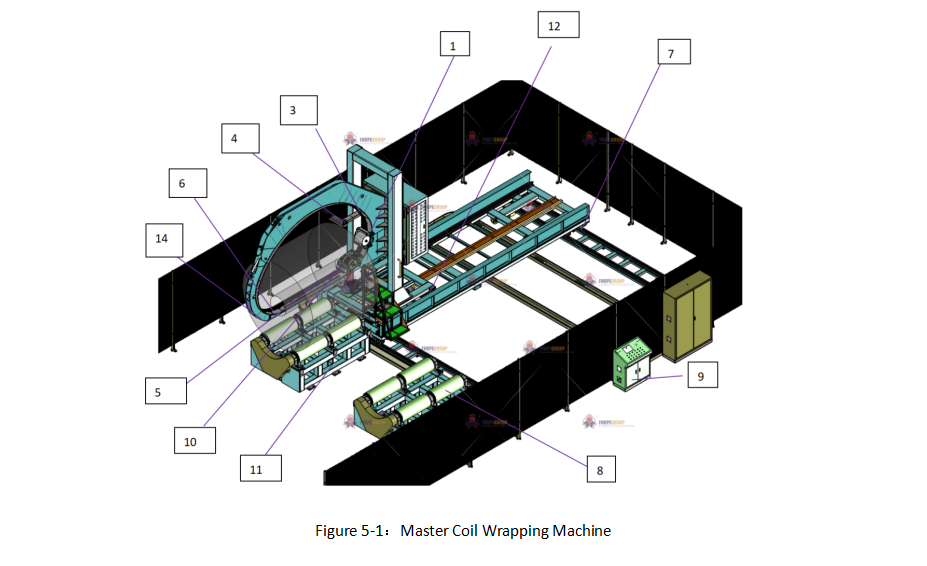
1. Tape Dispensers 2. Flexible orbital 3. Frame/Arch 4. Material Holder 5. Traction Unit 6. Bridge Section 7. Mobile Support Cart 8. Support Rolls 9. Control System 10. Servos 11. Platform 12. Trolley 13. Position Sensors 14. Locking Mechanism 15. Chain or Belt
Overview of MASTER Coil Wrapping Machines
Coil wrapping machines figure 5-1:master coil wrapping machine play a critical role in industries where large, heavy coils—such as metal sheets or wires—require secure packaging. These machines automate the wrapping process, ensuring that protective materials are applied consistently and efficiently. By automating this task, manufacturers can reduce labor costs, improve operational speed, and protect their products from damage during storage and transport.
Detailed Operation and Design of the Coil Wrapping Machine
This coil wrapping machine includes essential components like one or more tape dispensers (1), which move along a specially designed flexible orbital (2) (such as a chain or belt). The flexible orbital is driven by a motor and guided along the frame/arch (3) of the machine, allowing the carriage assembly to wrap material tightly around the coil.A key feature of this machine is its low-friction flexible orbital that enables smooth movement and efficient application of the wrapping material. The chain is guided through a profile that reduces friction and maintenance needs, making it highly reliable for continuous operation.
The wrapping materials, supported on a material holder (4), are applied to the coil with precision, thanks to the machine’s traction unit (5), which is positioned outside the arch for easy maintenance.
Bridge and Loading System
The machine’s bridge section (6) can be opened hydraulically, pneumatically, or electrically to load and unload coils. The bridge’s flexible design allows it to open from one or both sides, depending on space and installation constraints. This ensures that the coils can be loaded efficiently, with the bridge retracting to allow for quick changeovers. Once the wrapping process is complete, the flexible orbital is reconnected to the bridge through an automatic reverse operation.
Additionally, a mobile support cart (7) moves along tracks to feed the coils into the machine. The coils rest on support rolls (8), which rotate to ensure the wrapping material is applied evenly. The synchronized control system (9) ensures the carriage assembly and coil rotation speeds are coordinated, providing a smooth and slightly overlapping wrap that fully covers the coil with protective material.
Control and Synchronization
The machine is equipped with a control system, which allows operators to set and adjust various parameters through a manual control panel. This system regulates the speed of the motors that drive the flexible orbital, rotate the coils, and control the bridge section opening and closing mechanisms. The control system also adjusts the height of the frame/arch relative to the coil, ensuring that the wrapping process is perfectly aligned with the center of the coil.
Furthermore, the control system synchronizes the operation of multiple servos (10), ensuring that the flexible orbital and carriage assembly are securely locked in place before the bridge opens or closes. This precise control prevents any misalignment and ensures smooth, uninterrupted wrapping.
Versatility and Application
This coil wrapping machine is versatile and can be used to wrap a wide variety of materials, though it is particularly effective with tubular objects like sheet metal coils. The machine’s carriage assembly moves relative to the coil, applying the wrapping material with precision, creating an even, slightly overlapping layer for complete protection.
The platform (11) supporting the coil can rotate around an axis parallel to the coil’s central opening, ensuring uniform wrapping. Additionally, the wrapping station is mounted on a trolley (12) that moves along a path parallel to the coil’s axis, allowing for easy positioning and alignment with the machine’s bridge section.
Enhanced Automation and Control
The control system is enhanced with position sensors (13) on the trolley , which communicate the exact location of the coil to the control panel. This ensures that the trolley stops in the correct position for loading, wrapping, and unloading. The system also controls a Locking mechanism (14) that secures the flexible orbital (chain or belt) during the wrapping process, ensuring it is locked in place before wrapping begins.
Conclusion
In summary, this coil wrapping machine provides an advanced, automated solution for packaging large, heavy coils. With its flexible, low-maintenance design and synchronized control system, it offers reliable performance and enhanced efficiency in wrapping applications. By automating the wrapping, loading, and unloading processes, the machine not only improves productivity but also ensures consistent, high-quality protection for industrial products.
Related posts:
 horizontal coil stretch wrapping machine videos
 orbital stretch wrapper for pallet strapping and wrapping
 wire rod coil wrapping machine for sale
 Automatic aluminum tape packing machine video
 operation woven tape wrapping
 aluminum coil tilter and upender
 Horizontal Orbital Stainless Steel Coil Wrapping Machine
 Coil tilter and coil upnder
 Automatic wire coil compacting solution
 Steel Wire Coil Unwinding Machine