1. Introduction
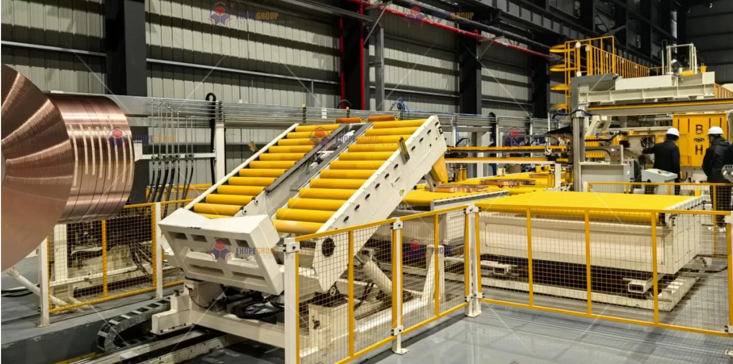
In the realm of steel coil processing, rigorous testing protocols are crucial to confirm that every piece of equipment—from the primary coil packing machine to the coil strapping machine and the coil stacking machine—performs at or above its designed specifications. These machines, powered by a combination of electric motors, servo systems, and hydraulic drives, must operate seamlessly under diverse conditions to maintain throughput, safety, and long-term reliability.
The testing phase is not merely a mechanical exercise; it is an integrated validation of system performance, safety interlocks, control algorithms, and materials durability. Comprehensive load testing is especially significant in verifying a packing line’s throughput capacity, operational precision, and conformance to international standards (e.g., ISO, EN, GB/T). This document offers an in-depth look at the multi-layered testing procedures that ensure a high-performing coil packing line, covering everything from subcomponent checks to final acceptance tests.
2. Overview of Testing Objectives
Before outlining the specific testing steps, it is helpful to state the overarching goals:
Validate Mechanical Robustness
- Confirm that frames, supports, and moving parts can withstand design loads (often up to 125% of nominal capacity) without permanent deformation or performance degradation.
- Evaluate fatigue life by simulating repeated cycles representative of normal production demands.
Ensure Electrical and Control Performance
- Verify that PLC logic, variable frequency drives (VFDs), servo motors, and sensor feedback loops consistently produce the intended motions and speeds.
- Conduct fault simulation to confirm safe shutdown sequences and emergency overrides.
Check Hydraulic Stability
- Ensure hydraulic cylinders and power units maintain the required clamping, lifting, or tensioning force within a specified tolerance (e.g., ±2.5%).
- Monitor for potential leaks, pressure drops, or temperature spikes under prolonged operation.
Guarantee Safety Compliance
- Validate compliance with machine directives (e.g., EN 415-8 for packaging machinery safety), ensuring all guards, interlocks, and emergency stops function instantly and reliably.
- Verify operator safety during coil handling, especially for heavy loads or rotating elements.
Confirm Production Throughput and Speed
- Conduct load and cycle tests that replicate real factory conditions, confirming that the line can meet or exceed nominal production rates (e.g., 15 coils/hour).
With these objectives in mind, the testing stage proceeds through carefully designed steps that leverage established engineering norms, instrumentation, and real-world scenarios.
3. Pre-Testing Preparations
3.1 Environmental and Setup Requirements
Controlled Ambient Conditions
- Temperature and humidity can affect hydraulic fluid properties, servo motor performance, and sensor calibration.
- Typical target environment: 20–25°C and relative humidity 40–60%.
Machine-Leveling and Foundation Checks
- Verify that the coil packing line is installed on a suitably rigid floor or foundation.
- Check alignment of rails, conveyors, and stacking tables to within ±1.0 mm across the entire length (per ISO 9283), ensuring consistent coil travel and minimal vibration.
Safety Protocols
- Confirm that safety curtains, gates, and emergency stops are energized and operational before energizing motors or hydraulic circuits.
- Lockout-Tagout (LOTO) procedures are enforced whenever technicians interface with electrical panels or hydraulic lines.
3.2 Instrumentation and Data Acquisition Setup
Accurate testing hinges on the right tools:
- Laser or Photogrammetry Systems: For measuring dimensional changes or positional errors in real time.
- Pressure and Flow Sensors: Tied into the hydraulic system to record performance under load, verifying compliance with ISO 4413 standards.
- Torque and Strain Gauges: Attached to servo shafts, coupling points, or critical weldments to quantify stress under dynamic loads.
- High-Speed Cameras: Useful for validating strapping tension or the uniformity of wrapping speeds in real time.
Data is collected through centralized systems like NI CompactDAQ or Rockwell FactoryTalk, ensuring synchronization of multiple sensor inputs. Historical logs allow for trend analysis and the detection of subtle anomalies.
4. Testing Phases and Methodologies
4.1 Subsystem Checks (No-Load Testing)
4.1.1 Mechanical Movement Verification
Roller Conveyors and Turntables
- Run the conveyor lines at various speeds (from slow jog to maximum rated velocity) to detect irregularities such as wobbling rollers or uneven rotation.
- Observe alignment, listening for gear meshing noise or belt slipping.
Hydraulic Cylinder Movement
- Perform low-pressure cycling of all cylinders (e.g., clamp and unclamp actions) to check for possible misalignment or slow response.
- Confirm that all valves (directional, proportional, or servo valves) open and close consistently.
4.1.2 Electrical and Control Validation
PLC Logic Sequence
- Step through each I/O point, verifying sensor signals (photo-eyes, limit switches, encoders) and corresponding PLC registers.
- Evaluate the correct functioning of subroutines, including safety sequences, alarm triggers, and motion profiles for servo drives.
Servo Motor Tuning
- Execute homing routines, checking that position references match physical zero points.
- Run open-loop and closed-loop tests at incremental speeds; record overshoot, settling time, and repeatability (target: ±0.1 mm, per VDI/DGQ 3441).
No-load testing serves as the foundation, ensuring that each subsystem is ready for the higher stress of load testing.
4.2 Integrated Testing (Partial and Full Load)
Once basic functionality is confirmed, technicians gradually introduce load scenarios to match the machine’s design envelope:
Load Simulation
- Employ steel coils of various diameters and weights, or use calibrated test blocks that mimic the mass distribution of actual coils.
- Start at ~50% nominal load, incrementally increasing to 100–125% to evaluate mechanical margins and safety factors (aligned with GB/T 3811-2008 for lifting equipment).
Hydraulic Stress Testing
- Ramp up system pressure to operational levels (e.g., 10–25 MPa).
- Check for leakage rates at couplings, manifold blocks, or cylinder seals using standardized detection fluids or ultrasonic leak detectors.
- Validate pressure-holding capacity for a specified duration (e.g., 10 minutes) with minimal drift (≤1.5% setpoint).
Conveyor and Transfer Mechanics
- Monitor line speeds to match the design throughput (e.g., 15 coils/hour).
- Use load cells or in-line torque sensors to confirm that drive motors can handle peak torque demands.
- Examine alignment to prevent coil offset or drifting that might lead to jam-ups or collisions.
Strapping Tension and Wrapping Consistency
- If the line includes a strapping machine, measure the tension variance (target: ±2.5% as per EN 12079-2) using calibrated tension meters.
- For stretch-wrapping operations, confirm film elongation rates (e.g., 300% ±5%), verified by a non-contact extensometer or digital tension gauge.
4.3 Specialized Testing Scenarios
4.3.1 Extreme Environmental Conditions
Temperature Stress
- If the client operates in very hot or cold climates (e.g., -10°C to +40°C), replicate these conditions in a controlled environment or run an extended soak test.
- Evaluate hydraulic fluid viscosity changes and servo driver thermal thresholds.
Humidity and Corrosion
- In regions prone to high humidity or salt spray (coastal operations), apply test standards like ASTM B117 for salt spray or ISO 9227 for corrosion testing.
- Ensure protective coatings (e.g., galvanization, Aluzinc coatings) stand up to prolonged exposure.
4.3.2 Continuous Operation Endurance Tests
24-Hour Run
- Operate the coil packing line continuously under normal operating loads for a full day (or longer) to detect any progressive faults such as overheating in motors, drifting sensor calibration, or hydraulic fluid aeration.
- Track real-time data trends for torque, pressure, temperature, and vibration, flagging anomalies for immediate intervention.
Emergency Stop and Power Loss
- Simulate sudden power cuts to ensure motors and cylinders transition to safe positions without coil slipping or dropping.
- Confirm that the emergency stop (E-stop) system can arrest all motion within the required time, typically ≤50 ms from safety gate activation (aligned with EN 1088:1995).
5. Measured Parameters and Acceptance Criteria
To make testing meaningful, each parameter must have clear acceptance thresholds. Below is a representative table of critical metrics:
| Test Category | Standard/Reference | Acceptance Criteria | Measurement Method |
|---|---|---|---|
| Coil Packing Speed | JB/T 10231-2016 | ≥15 coils/hour (Φ1200 mm steel coil) | Encoder feedback + Timer |
| Strapping Tension Accuracy | EN 12079-2 | ±2.5% of nominal tension | Digital Tension Sensor |
| Hydraulic Pressure Stability | ISO 4413 | Drift ≤1.5% over 10-minute hold | Pressure Transducer + Data Log |
| Servo Position Repeatability | VDI/DGQ 3441 | ±0.1 mm or better | Laser Interferometer / Dial Gauge |
| Noise Level | ISO 4871:1996 | ≤78 dB(A) at 1 m | Calibrated Sound Level Meter |
| Safety Gate Response | EN 1088:1995 | Stop Delay ≤50 ms | Oscilloscope Trace |
| Energy Efficiency | ISO 14955-1 | ≤0.8 kWh/ton of steel coil | Power Analyzer (0.5% accuracy) |
If any parameter deviates from these acceptance thresholds, the engineering team investigates root causes—be it an alignment issue, control loop tuning problem, or hydraulic seal defect—and re-tests the line once remedial actions are taken.
6. Data Analysis and Documentation
6.1 Real-Time Monitoring and Storage
Modern coil packing lines often incorporate industrial IoT solutions, enabling real-time monitoring of mechanical, electrical, and hydraulic parameters. Data from sensors (pressure, torque, encoder position, temperature) is fed into a centralized SCADA system or a distributed control platform (e.g., Rockwell FactoryTalk or Siemens WinCC).
Data Logging Frequency
- Vibration or pressure spikes require high-frequency logging (up to 1 kHz) for accurate capture.
- Slower processes (e.g., coil conveyance) can log at a lower rate (1–10 Hz).
Automated Alarms and Trend Analysis
- System triggers alarms when values exceed preset thresholds (e.g., servo torque 110% of nominal capacity).
- Trending data helps identify progressive wear or drift, guiding preventive maintenance strategies.
6.2 Final Acceptance Test (FAT) Protocol
Upon successful completion of integrated and specialized tests, a comprehensive FAT is conducted with customer representatives. This step includes:
Functional Demonstration
- Running the line through its full operational sequence: loading a coil, conveying, strapping, wrapping (if applicable), stacking, and unloading.
- Showcasing correct HMI displays, fault messages, and safety logic.
Review of Key Performance Indicators (KPIs)
- Comparing measured packing speed, tension consistency, and downtime frequency against contractual or design commitments.
- Documenting the stable operation with full load for a continuous shift (e.g., 8 hours).
Sign-Off and Documentation
- Customers receive a comprehensive test dossier, including measured data charts, calibration certificates for test equipment, and system user manuals.
- Any open points or minor nonconformities are noted in a punch list with target resolution dates.

7. Lifecycle Perspective: Post-Testing and Maintenance
7.1 Transition to Operational Phase
Once testing proves the machine meets specifications, it is typically shipped to the production floor. However, the testing mindset does not end there. In many modern facilities, the approach is to embed predictive maintenance and ongoing verification:
Online Condition Monitoring
- Permanent sensors track critical parameters like bearing vibration, motor current, hydraulic oil contamination (ISO 4406 class checks), etc.
- Analytical software employs machine learning to detect emergent failures before a catastrophic breakdown occurs.
Scheduled Calibration
- Torque wrenches, laser alignment tools, and tension sensors require recalibration at specified intervals to maintain measurement integrity.
- PLC logic backups and versioning (IEC 61131-3 compliance) ensure any code modifications are properly documented.
7.2 Continuous Improvement
Feedback from real-world use is invaluable. Common improvements identified post-deployment might include:
- Refining Hydraulic Actuators
- Upgrading seals or switching to higher-grade oils to reduce wear and temperature fluctuations under extreme loads.
- Optimizing Control Loops
- Adjusting servo tuning parameters to reduce overshoot or fine-tuning strapping tension profiles for more delicate coil edges.
- Enhancing Ergonomics and Safety
- Adding ergonomic designs for coil loading or improving guard placements to reduce operator strain and risk.
8. Testing Innovations and Future Trends
8.1 Digital Twin and Virtual Commissioning
Many fabricators are moving toward digital twins—creating a virtual model of the entire coil packing line using software like Siemens NX Mechatronics Concept Designer (MCD). This allows:
- Shortened Physical Testing Time
- By debugging PLC logic, servo motion, and safety interlocks in a virtual environment, you can catch errors before machinery is built.
- Machine Learning Integration
- Real-world data continuously updates the digital twin, refining predictive algorithms that forecast mechanical or control anomalies.
8.2 Multi-Physics Testing Platforms
For lines subjected to extremely varied operational environments:
- Simultaneous Monitoring
- Vibrations in the 0–10 kHz range, fluid pressures up to 35 MPa, temperature readings from -20°C to +150°C, and servo drive feedback can be tracked in parallel.
- Comprehensive Diagnostics
- Advanced software correlates these multi-physics datasets, pinpointing subtle interactions that might trigger micro-failures or performance drifts.

9. Summary and Key Takeaways
The testing process for a steel coil packing line is multifaceted, aiming to confirm the machine’s structural integrity, operational consistency, and safety under real-world conditions. It encompasses everything from no-load checks to 24-hour endurance trials, each governed by international standards such as GB/T 3811, ISO 4413, and EN 12079-2. By establishing clear acceptance criteria—target tension levels, positional accuracy, pressure stability, noise thresholds, and more—fabricators can demonstrate tangible proof of reliability to customers.
Key highlights:
- Thorough Preparation: Controlling the test environment and verifying instrumentation are critical for credible results.
- Gradual Load Introduction: Systematically ramping from no-load to 125% capacity ensures progressive validation of each subsystem.
- Data-Driven Documentation: Real-time monitoring and robust logging enable traceability, revealing both immediate and long-term performance trends.
- Standards Compliance: Meeting or exceeding ISO, EN, IEC, and GB/T codes fosters trust and aligns with global best practices.
- Lifecycle Emphasis: Testing is not an isolated event—it lays the groundwork for predictive maintenance, future upgrades, and continuous improvement.
Whether you are a customer seeking assurance of operational safety or an engineer responsible for final commissioning, the testing procedures outlined here underscore a commitment to delivering a cutting-edge, robust coil packing solution. In essence, these protocols champion a philosophy: consistent quality and reliability emerge from a disciplined, standards-based approach to every stage—from design and assembly to the final handshake of validated performance.
Final Note:
This guide reflects proven best practices for testing coil packing lines, leveraging international codes and real-world data analysis. Actual testing plans may be further customized based on site-specific requirements, advanced material selections, or specialized design features. Always consult the project’s official test protocols and engineering documentation to address unique production demands and regulatory frameworks.