1. Introduction
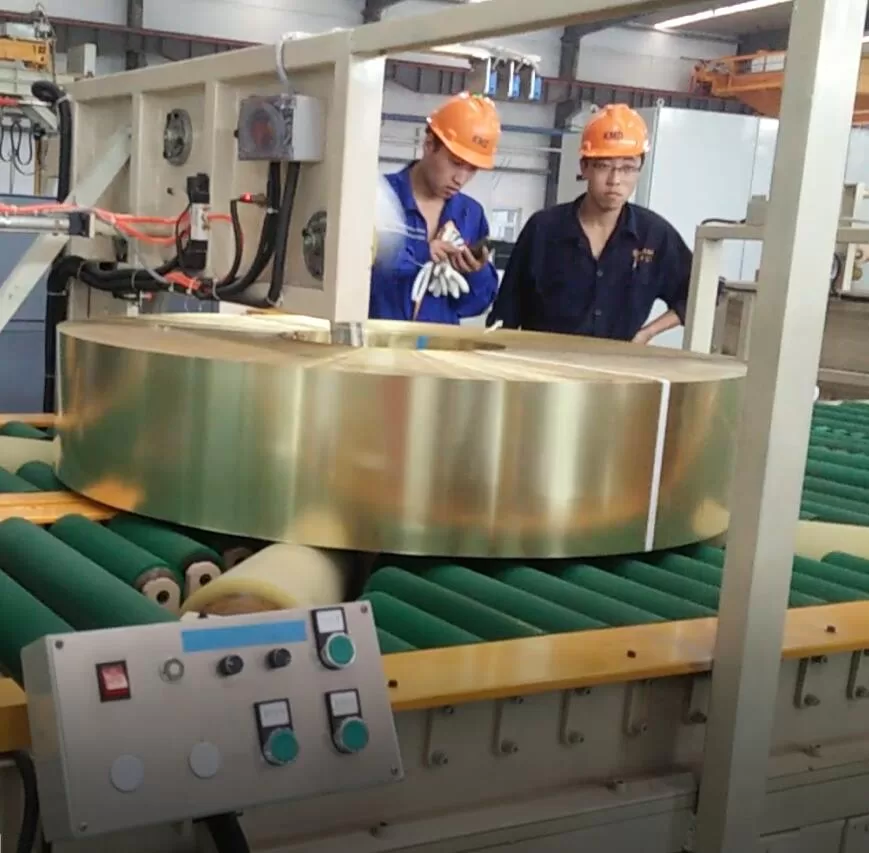
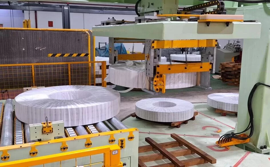
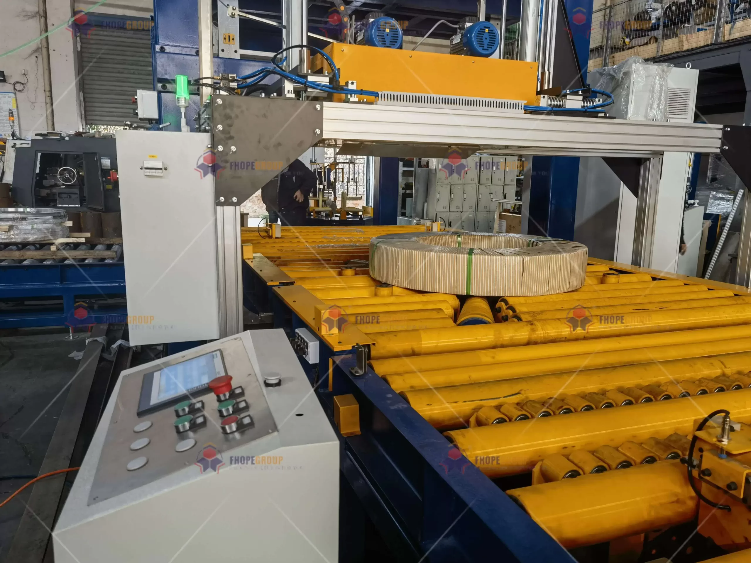
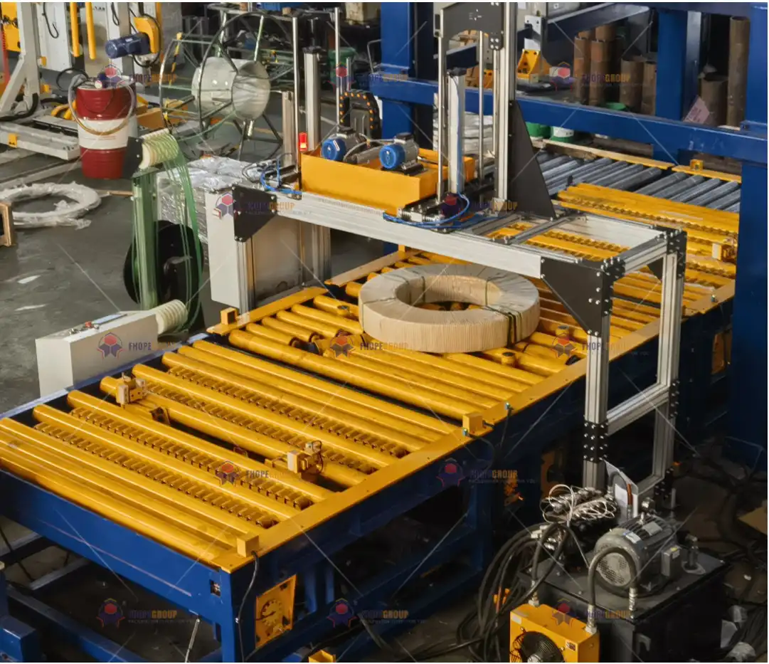
In industrial settings where steel coils undergo packaging, strapping, and stacking, precision and consistency are vital for reliable, high-volume operations. A typical coil packing line comprises multiple machines—such as the coil packing machine, coil strapping machine, and coil stacking machine—each driven by electric motors, servo systems, or hydraulic actuators. These are all orchestrated by a sophisticated control system, typically including PLCs (Programmable Logic Controllers), VFDs (Variable Frequency Drives), and advanced servo motors.
For this sophisticated arrangement to function seamlessly, the program debugging phase is indispensable. Debugging ensures the correct interactions among mechanical assemblies, sensors, drives, and user interfaces; it fine-tunes the myriad control loops, safety interlocks, and motion profiles to guarantee stable operation and throughput. In essence, program debugging melds mechanical design norms with control logic to uphold safety, optimize cycle times, and maintain robust performance over the system’s operational lifecycle.
This document demystifies the intricacies of program debugging for a coil packing line, referencing established international standards like ISO 9283 (robotics and motion accuracy), IEC 61131-3 (PLC programming languages), VDI 2206 (mechatronic system guidelines), and EN 415-10 (safety of packaging machinery). The goal is to give a comprehensive view of how an integrated debugging procedure leverages virtual modeling, real-time data analysis, and iterative tuning to deliver consistent, fault-tolerant functionality.
2. Debugging Framework: Mechanical–Control Cohesion
2.1 Coordinating Mechanical and Control Systems
A coil packing line blends robust mechanical hardware—frames, cylinders, gearboxes, rollers—with advanced electronics and software-driven logic. Achieving stable performance demands a close synergy between these domains. For instance:
Servo Acceleration and Jerk Management
- Rapid acceleration (and deceleration) must be configured in the servo drive to avoid undue mechanical stress.
- Standards like IEC 61800-7 specify maximum jerk values (e.g., ≤50 m/s³) that help reduce vibration and extend component life.
Hydraulic Response and Control
- Hydraulic systems often clamp, lift, or rotate heavy coils. Correct response times—often measured as the delay to reach 90% of set pressure—should be ≤0.8 s (per ISO 10767-1), ensuring precise synchronization with servo-driven actions.
Safety Interlocks
- Emergency stops, safety gates, and guard interlocks must be integrated into the control logic with minimal delay.
- EN 60204-1 mandates e-stop signal transmission delays ≤20 ms to safeguard operators and equipment.
2.2 Materials Interaction and Sensor Compatibility
In debugging, it is crucial to validate that the sensors and mechanical parts interact reliably under operational stresses:
Substitute Load Materials
- Instead of actual steel coils during the initial debugging, standardized test masses (e.g., Q235B steel blocks with a known density of 7.85 g/cm³) can be used. This mitigates risk and allows for repeatable test routines.
Friction and Wear Simulations
- Rolling elements might see friction coefficients below 0.15 (ASTM D1894) if PTFE or specialized low-friction coatings are used. Testing ensures that PLC logic accounts for real-world friction changes over time.
Temperature Tolerance
- If cables, servomotors, or sensors operate near heat sources, verifying insulation endurance (e.g., 200°C for 1,000 hours in accordance with IEC 60811-201) is vital for stable signal integrity.
Through these checks, debugging transitions from purely software-based parameter tuning into an integrated approach that addresses mechanical stability, materials performance, and control logic reliability.
3. Debugging Workflow: From Simulation to Live Adjustment
The debugging sequence typically proceeds through four core stages. Each stage leverages specialized engineering tools and test methodologies, refining the program’s logic and performance metrics at progressively deeper levels.
3.1 Digital Twin Pre-Debugging
Digital twin or virtual commissioning techniques are becoming widespread in modern fabrication facilities. Using platforms like MATLAB/Simulink, Siemens NX MCD, or TIA Portal for virtual environments:
Control Logic Modeling
- PLC, motion controller, and drive profiles can be mapped to a simulation environment.
- Engineers verify state transitions, I/O responses, and motion curves before physical hardware is energized.
Collision and Kinematics Checks
- Virtual collision detection ensures that mechanical arms, coil lifters, or strapping heads do not exceed their design envelopes.
- Kinematics simulations evaluate how changes in servo torque or hydraulic pressure might affect coil travel paths.
Predictive Optimization
- Early-stage debugging leverages advanced algorithms (e.g., NSGA-II for multi-objective optimization) to balance speed, tension control, and safety margins.
- By frontloading these improvements in the virtual domain, on-site debugging time may drop by up to 40%.
3.2 Subsystem Closed-Loop Tests
After virtual validation, the next stage targets each subsystem in physical form:
Servo Motor Inertia Identification
- Many modern servo drives have built-in routines to identify load inertia, refining control gains for stable motion.
- The goal is to achieve minimal overshoot and short settling times.
Hydraulic Proportion and Servo Valve Response
- Step-response testing for hydraulic actuators measures how quickly and accurately the system pressurizes.
- Data from these tests feed back into the PLC’s closed-loop PID or feedforward algorithms, ensuring cohesive movement with the servo-driven sections.
Sensors and Actuators
- Proximity sensors, photoelectric switches, or load cells must be tested individually.
- If a sensor’s trigger point or threshold is off, it can lead to misaligned coil loading or erroneous cycle starts.
3.3 Integrated System Debugging
With each subsystem validated, engineers unify them under the main PLC program:
HMI–PLC–VFD Collaboration
- The Human-Machine Interface (HMI) orchestrates operator commands, while the PLC interprets them and dispatches signals to VFDs or servo drives.
- Debugging ensures that speed references, run/stop signals, and fault interlocks align perfectly. For instance, a mismatch in reference scaling could cause roller conveyors to run too fast or too slow, misaligning coil flow.
Packaging Film Tension Control
- In lines that apply stretch film, tension must remain within ±2% of the setpoint (per EN 12079-1 or similar guidelines).
- The PLC can use feedforward control combined with real-time tension feedback to maintain consistency despite coil diameter changes.
Timing Synchronization
- Large lines often rely on distributed control hardware, requiring near-microsecond synchronization (IEC 61158-2) to ensure smooth transitions as coils move from packing to strapping or stacking.
3.4 Operational Scenario Optimization
Once the integrated line cycles correctly, engineers refine performance:
Production Rate Tuning
- Gradually ramp the line up to the maximum rated throughput (e.g., 15 coils/hour) while monitoring motor torque, fluid pressures, and sensor latencies.
- If surges or collisions occur, it may necessitate adjusting servo ramp times or buffer distances.
Genetic Algorithm or Heuristic Adjustments
- Advanced lines may incorporate parametric optimization (e.g., using a genetic algorithm or gradient-based approach) to discover ideal control parameters that yield the shortest possible cycle time without surpassing mechanical stress thresholds.
Energy Consumption Minimization
- Identifying idle power usage, adjusting VFD deceleration ramps, or employing servo sleep modes during production lulls can cut energy usage by more than 10–15%.
- Formal guidelines like ISO 14955-2 define strategies for machine tool energy efficiency, which can be adapted for packaging lines.

4. Lifecycle Debugging Management
4.1 Design Verification Stage
Most debugging starts conceptually, in parallel with design:
PLC Program Virtualization
- With advanced platforms like Siemens TIA Portal, logic blocks can be simulated with digital I/O or virtual drives.
- Reduces physical prototyping costs by verifying basic logic sequences—emergency stops, interlocks, sensor gating—before hardware is installed.
Multibody Dynamics Simulation
- Tools like ADAMS or RecurDyn handle more detailed mechanical events, checking contact forces, joint stress, or coil inertia in transitions.
- Minimizing mechanical shock (±5% margin) lowers the risk of structure fatigue or weld cracking over the machine’s lifetime.
4.2 Manufacturing Process Control
During manufacturing, each stage of production can be accompanied by incremental debugging:
Real-Time Data Monitoring
- Sub-second sampling (e.g., 5–10 ms intervals) logs parameters like servo current, hydraulic pressure, or position offset.
- Tools such as LabVIEW FPGA or NI CompactRIO help capture data at high frequencies for advanced signal analysis.
Version Control
- PLC code changes are archived in repositories (like Git) compliant with IEC 61131-3 guidelines, enabling rollbacks if newly introduced changes cause regressions.
- Timestamps in ISO 8601 format ensure clarity about which version was deployed and when.
Shop Floor Traceability
- Each program iteration is documented with the machine’s current state—drive parameters, sensor calibrations, and hardware changes.
- If a future fault arises, technicians can reconstruct the machine’s state at any past checkpoint for root-cause analysis.
4.3 Operational Phase and Intelligent Upgrades
In live production, debugging transforms into continuous improvement:
Self-Optimization
- Some coil packing lines incorporate model-predictive control or adaptive algorithms that auto-tune setpoints in real time, improving throughput or reducing film usage by ~15%.
- Coupled with a digital twin, the system can run “what-if” scenarios offline before implementing changes on physical equipment.
OPC UA for Data Access
- Standardized communication per IEC 62541 permits cross-platform data sharing—operators, engineers, or even remote service providers can access historical logs or adjust parameters securely.
5. Standardized Debugging Protocol
To ensure consistent, systematic debugging, most fabricators adopt a standardized protocol referencing recognized norms. A representative table might look like this:
| Debugging Category | Relevant Standard | Acceptance Criterion | Verification Method |
|---|---|---|---|
| Motion Trajectory Accuracy | ISO 9283:1998 | Path repeatability ≤ ±0.3 mm | Laser tracking (e.g., API Radian) |
| Timing Synchronization | IEC 61158-2 | Clock skew ≤1 μs across subsystems | Precision Time Protocol (PTP) logging |
| Film Tension Control | EN 12079-1 | Fluctuation range ±2% of set tension | Real-time force sensor (HBM S9M) |
| Energy Optimization | ISO 14955-2 | No-load power ≤15% of rated capacity | Power quality analyzer (e.g., Fluke 435) |
| Safety Logic Latency | EN 60204-1 | E-stop signal < 20 ms delay | Oscilloscope or high-speed data capture |
If a machine fails to meet these criteria, it re-enters a debugging sub-loop. Engineers isolate the cause—be it a PID gain, servo jerk limit, or misaligned sensor bracket—and correct the configuration or mechanical arrangement before retesting.
6. Smart Debugging Innovations
6.1 Multi-Objective Optimization Algorithms
As coil packing lines grow more complex, single-parameter optimization (e.g., just speed or tension) becomes insufficient. Multi-objective algorithms (like the Non-dominated Sorting Genetic Algorithm II, NSGA-II) can juggle multiple performance metrics—speed, tension consistency, energy usage, safety margins—while generating a Pareto front of optimal solutions. When integrated with a digital twin:
- Reduced Tuning Time
- Instead of laboriously trial-and-erroring each parameter, the algorithm swiftly converges on near-optimal sets.
- Enhanced Accuracy
- The best solutions often reduce the cycle time by up to 20–30% without raising mechanical stress or risking coil misplacement.
6.2 Augmented Reality (AR) Debugging
Emerging AR technologies superimpose digital data—sensor readings, servo waveforms, machine states—onto the actual machine:
Live PLC Variable Visualization
- Using an AR headset (e.g., Microsoft HoloLens), technicians see servo current or tension sensor values updated at ≥60 Hz in their field of view.
- Potential anomalies (e.g., vibrations beyond a normal band) appear as heat maps on the physical equipment.
Remote Expert Assistance
- An off-site specialist can watch the same AR feed, marking areas in the technician’s view that may need mechanical adjustment or parameter changes.
- This shortens downtime since expertise can be provided without physically traveling to the site.
7. Concluding Remarks
Program debugging for a coil packing line transcends the mere act of toggling bits or adjusting a single speed setpoint. Instead, it encompasses a comprehensive lifecycle approach—initial design verification, subsystem calibration, integrated system optimization, and continuous refinement during operation. By leveraging digital twins, advanced control algorithms, high-speed data acquisition, and augmented reality, fabricators can minimize commissioning time while maximizing performance, safety, and reliability.
Key Takeaways:
- Holistic Mechanical-Control Integration: Validate servo motor jerk limits, hydraulic response times, and sensor thresholds for cohesive, conflict-free operation.
- Iterative Debugging Workflow: Start with virtual models, then progress through subsystem and integrated testing to refine performance step by step.
- Lifecycle Data Management: Employ version control (Git) and standardized data logging, ensuring any future modifications or fault diagnoses have a robust audit trail.
- Standards Alignment: Meeting or exceeding references like ISO 9283, IEC 61158, EN 60204-1, and VDI 2206 fosters trust in global markets and reduces liability.
- Continuous Improvement and Innovation: Tools like multi-objective optimization algorithms and AR-based debugging keep the coil packing line agile in response to evolving production demands.
By adhering to recognized best practices and maintaining a forward-looking perspective on emerging technologies, the debugging phase becomes a strategic lever for delivering excellence. When done right, program debugging for a coil packing line doesn’t just ensure the machine works as intended—it establishes a robust foundation for long-term operational success, safety, and adaptability.
Final Note:
While this article synthesizes core debugging principles, each facility or project may demand unique tests or specialized hardware considerations. Always consult the official engineering documentation, relevant regional regulations, and internal corporate standards to craft a tailor-made debugging plan that aligns precisely with specific production goals.