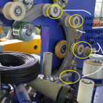
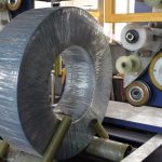
1. Introduction and Core Material Selection Strategy
Coil packing lines are critical in many sectors, especially in steel service centers, metal processing facilities, and manufacturing plants that handle heavy steel coils. The equipment involved—packing machines, strapping machines, and stacking devices—faces continuous loads, variable speeds, fluctuating environmental conditions, and high-cycle fatigue stresses. Additionally, with the integration of motors, hydraulics, PLCs, servo drives, and inverters, the system must also account for dynamic behaviors and precise motion control.
1.1 Material Selection Logic Framework
To achieve optimum system performance over the product’s lifecycle, our material selection process is governed by three primary dimensions:
| Selection Dimension | Quantitative Index | Verification Standard |
|---|---|---|
| Structural Durability | Tensile Strength ≥ 500 MPa (ASTM E8) | TÜV-Certified Fatigue Test (1×10⁶ cycles) |
| Dynamic Response Matching | Elastic Modulus Tolerance ≤ ±5% (aligned with system’s natural frequency) | ANSYS Harmonic Response Analysis Report |
| Life-Cycle Cost | MTBR ≥ 3000 h + Recycling Factor ≥ 85% (ISO 14040) | Comprehensive Cost Model Calculations |
Structural Durability: We emphasize the tensile strength of each structural element. For components subject to heavy loads and cyclical stresses, we subject them to standardized fatigue testing (1×10⁶ cycles or more) under TÜV certification to ensure long-term reliability.
Dynamic Response Matching: With servo motors, inverters, and PLC-based controls, it is crucial that the selected materials align with the system’s inherent resonant frequencies. We utilize ANSYS harmonic response simulations to confirm that the elasticity of steel, or of composites, interacts optimally with the drive system.
Life-Cycle Cost: By aiming for maintenance intervals (MTBR) above 3000 hours and a recycling factor of at least 85%, we minimize total ownership costs. This is supported by standardized LCA (Life-Cycle Assessment) metrics in accordance with ISO 14040.

2. Main Structural Materials
2.1 Steel Structure Selection Matrix
In the design of a coil packing line, steel is often the go-to material for frameworks, support arms, and tension-bearing shafts. However, not all steel grades are the same. Below is a matrix illustrating the steels we use, depending on specific loading scenarios:
| Operating Scenario | Material Option | Key Technical Indicators |
|---|---|---|
| Heavy-Duty Load Frame | Q690D High-Strength Steel (EN 10025) | -20 °C Impact Energy ≥ 55 J Shot Blasting to Sa 2.5 (ISO 8501-1) |
| High-Speed Motion | 42CrMo4 (DIN 17200) | Core Hardness: 32–38 HRC Surface Nitriding Depth: 0.3 mm (DIN 50190) |
| Corrosion-Resistant Parts | 316L Stainless Steel (ASTM A240) | NaCl Salt Spray Corrosion Rate < 1 mm/500 h (ISO 9227) Electrolytic Polishing to Ra ≤ 0.8 μm |
- Heavy-Duty Load Frame: Q690D steel supports the primary loading demands in our system. Its high tensile strength and excellent impact energy absorption (especially at subzero temperatures) make it suitable for areas subjected to heavy-duty loads, such as coil lift columns or robust machine bases.
- High-Speed Motion: For fast-moving parts—like rotating shafts, pinions, or other transmission components—42CrMo4 steel is heat-treated to achieve the correct balance of core strength and surface hardness. Nitriding processes enhance its wear resistance.
- Corrosion-Resistant Parts: Certain sub-assemblies may operate in humid or chemically-aggressive environments. For instance, strapping machine guide rails or external frames can be fabricated from 316L stainless steel for enhanced corrosion resistance. Electrolytic polishing further reduces surface roughness, mitigating contamination and wear.
2.2 Non-Metal Materials
While steel forms the foundation of most of the load-bearing structures, non-metallic materials play an equally significant role in sealing, buffering, and wear-reducing applications.
| Material Type | Application | Key Performance Indicators |
|---|---|---|
| Engineering Polyurethane (PU 95A) | Cushioning Pads | Compression Set < 5% after 72 h at 70 °C (ISO 1856) Shore Hardness Deviation ±2 A (ISO 7619-1) |
| Ultra-High Molecular Weight Polyethylene (UHMWPE) | Guide Rails | Wear Rate < 0.01 mm/km (ASTM D732) Dry Friction Coefficient μ ≤ 0.15 (ISO 8295) |
| FKM (Fluoroelastomer) | Seals and Gaskets | Operating Temperature: –25 °C to 230 °C (ASTM D2000) Volume Swell in ASTM #3 Oil < 5% (ISO 1817) |
- PU 95A: Often used for pads, shock absorbers, and buffers around coil edges. With a low compression set, these polyurethane elements sustain repeated loading without permanent deformation.
- UHMWPE: Ideal for guide rails or sliding supports due to its high wear resistance and low friction coefficient.
- FKM Seals: Critical in hydraulic and pneumatic systems, ensuring minimal leakage under high pressures and temperatures.
3. Key Moving Parts: Selection Norms
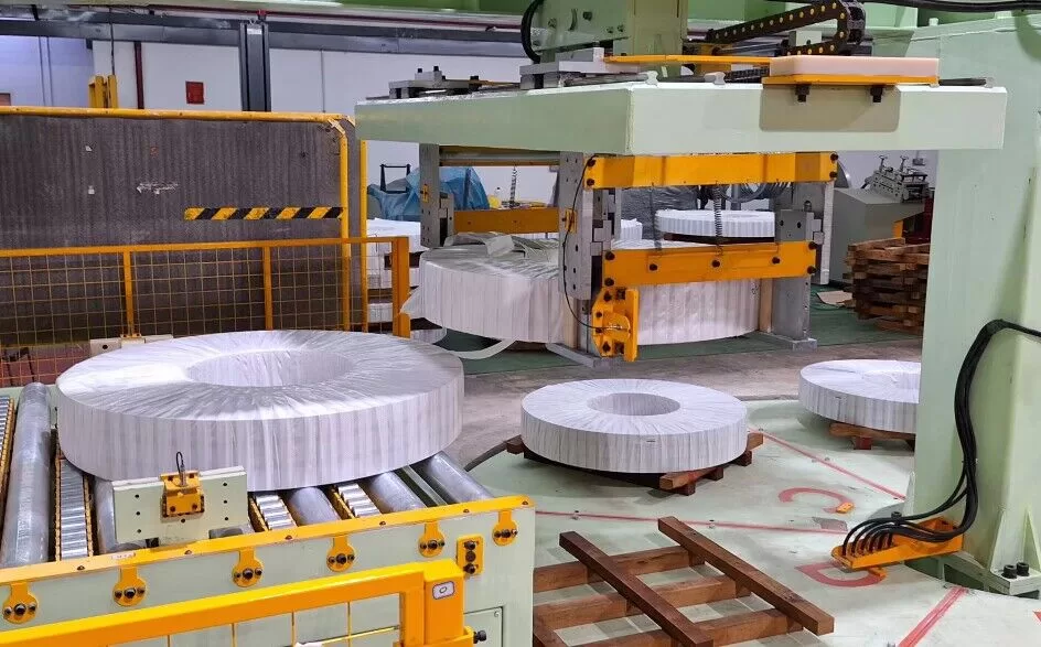
In a coil packing line, several high-stress moving assemblies ensure the coil is securely packed, strapped, and stacked. Here, gears, bearings, cylinders, and servo-driven actuators must be precision-manufactured and rigorously tested.
3.1 Power Transmission System
Gear Sets
- Carburizing and Quenching: We typically choose 20CrMnTiH (DIN 17210) for gears, subjecting it to a surface hardening range of 58–62 HRC. This ensures the gear’s outer layer withstands wear while the core retains toughness.
- Grain Size: We monitor grain size at 6–8 grade (ASTM E112) to maintain a fine, uniform microstructure, essential for resisting fatigue.
- Gear Grinding: Post-heat-treatment, grinding to DIN 3962 Class 6 is performed, improving gear meshing accuracy and reducing operational noise.
High-Load Bearings
Bearings see loads in multiple directions, and consistent performance requires both robust materials and precise finishing.
| Bearing Type | Material | Strengthening Process | Verification |
|---|---|---|---|
| Crossed Roller Bearing | GCr15SiMn | Bainitic Isothermal Quenching | Verified via SKF ABLT-7 Life Calculation |
| Linear Guide | SUJ2 High-Carbon Chromium Steel | Vacuum Degassing | Preload Loss ≤ 5% (ISO 14728) |
- Crossed Roller Bearings: Offer high rigidity and precision for rotary tables and manipulator arms. Bainitic isothermal quenching extends fatigue life under oscillating loads.
- Linear Guides: Often integrated in strapping or stacking modules where stable linear motion is crucial. SUJ2 steel with vacuum degassing prevents impurities that might cause premature pitting or flaking.
3.2 Hydraulic and Pneumatic System
Cylinder Rod Material Upgrade
Hydraulic cylinders and pneumatic actuators play a central role in coil clamping, stacking, or final alignment. Cylinder rods must endure mechanical stress, corrosion, and seal friction.
- Conventional Option: 40Cr (tempered steel).
- Upgraded Option: 17-4PH (precipitation-hardened stainless steel).
| Indicator | Conventional (40Cr) | Proposed (17-4PH) | Performance Gain |
|---|---|---|---|
| Tensile Strength | ~980 MPa | ~1310 MPa | ↑34% |
| Salt Spray Test | Rust after 500h | No Corrosion after 2000h | 4× |
| Fatigue Life | 1×10⁷ cycles | 3.5×10⁷ cycles | 3.5× |
Seal Combinations
- PTFE + Aramid Fiber Composite: We frequently use these advanced seals for their high resistance to extrusion under ≥350 bar pressure.
- Leakage Control: Achieved by maintaining static leakage below 0.1 mL/h and dynamic leakage under 0.5 mL/h (ISO 6194).

4. Advanced Materials and Surface Processing Technologies
In order to increase part longevity while managing costs, we employ selective surface processing techniques. These processes significantly improve wear resistance, reduce friction, and counteract corrosion.
4.1 Surface Hardening and Coating Methods
| Process Type | Suitable Parts | Core Parameters | Performance Gain |
|---|---|---|---|
| High-Velocity Oxy-Fuel (HVOF) | Transmission Shafts | WC-12Co Coating Thickness: 0.2–0.3 mm | 8–10× Wear Resistance (ASTM G65) |
| Plasma Nitriding | Gear Meshing Surfaces | White Layer Thickness: ~0.015 mm Surface Hardness ≥ 1100 HV0.5 | 3× Increase in Micro-Pitting Resistance (FZG) |
| Micro-Arc Oxidation (MAO) | Aluminum Bases | Ceramic Layer Porosity < 5% Thickness: 50–80 μm | 20× Improvement in Electro-Corrosion Resistance |
- HVOF: Commonly used for critical shafts exposed to abrasive conditions. The tungsten carbide-cobalt (WC-Co) layer effectively resists abrasive wear, while maintaining dimensional stability.
- Plasma Nitriding: Selectively strengthens gear contact surfaces. The ultra-hard nitride layer enhances load capacity in high-torque transmissions.
- Micro-Arc Oxidation (MAO): We use this for certain aluminum components, such as support brackets or motor housings, creating a ceramic-like layer that resists corrosion even under high-voltage or potential difference conditions.
4.2 Composite Materials
Carbon-Fiber-Reinforced Nylon (CF-PA66)
- Application: High-speed pick arms or guiding elements.
- Benefit: A significantly higher strength-to-weight ratio than aluminum. CF-PA66 exhibits 450 MPa/(g·cm³) in terms of specific strength, and dynamic stiffness up to 120% higher than conventional aluminum.
Metal Matrix Composites (AlSiC)
- Application: Damping substrates or vibration-prone housings.
- Thermal Expansion: ~19×10⁻⁶ /°C, nearly matching steel, enabling cohesive integration within the system.
- Noise Attenuation: ~15 dB(A) noise reduction at 2000 Hz, providing a quieter working environment.
5. Reliability and Validation Testing
Selecting premium materials is only half the story; rigorous validation is crucial to confirm that the design meets or exceeds real-world operational demands.
5.1 Laboratory Testing Norms
| Testing Category | Test Items | Equipment | Acceptance Threshold |
|---|---|---|---|
| Mechanical Performance | Low-Cycle Fatigue | MTS 810 Servo-Hydraulic System | ≥150% of Design Cycles |
| Microstructure Analysis | SEM Imaging | FEI Quanta 250 FEG | Non-Metallic Inclusions ≤ B1 (DIN 50602) |
| Chemical Composition | Optical Emission Spectroscopy | OES Foundry-Master Pro | Alloy Deviation ≤ ±0.5% |
- Low-Cycle Fatigue: We validate load-bearing parts under cyclical loading to ensure they can surpass the design cycles by at least 50%.
- SEM Analysis: To confirm the material’s purity, uniformity, and detect any micro-cracks or inclusions that could propagate under stress.
- Chemical Composition: Each alloy batch is tested before production. A deviation beyond ±0.5% of the target composition triggers a corrective action.
5.2 Digitalized Materials Database
We maintain a cloud-based repository that holds over 15,000 sets of material properties. Engineers continuously update this database with:
- Stress-Strain Curves: Digitized models for both static and dynamic load conditions.
- S-N Fatigue Curves: Fitted formulas for each alloy or composite, enabling more accurate life predictions.
- Process Parameter History: Full traceability of heat treatment cycles, foundry batch IDs, and test results.
The digitalization effort ensures that each coil packing line design iteration is built on real-world data, reducing guesswork and refining material choices over time.
6. Typical Application Case Comparisons
To highlight the practical benefits of our selection methodology, here are some direct comparisons between traditional material usage and our optimized choices:
| Project Parameter | Traditional Material/Approach | Optimized Material/Approach | Real-World Benefit |
|---|---|---|---|
| Packaging Machine Lift Column | Q235 Carbon Steel + Standard Lubrication | Laser-Cladded Ni-Based Alloy + Solid Lubricant Coating | Maintenance-Free Interval Extended to 5 Years |
| Hydraulic Valve Block | Ductile Iron (Grade GGG40) | High-Density Vermicular Graphite Iron (GJV400) | Pressure Fluctuation Reduced by 40% |
| Turntable Bearing | 45# Steel, Standard Quench | Duplex Stainless Steel 2205 (PREN≥35) | 7× Service Life in Saltwater Environments |
| Key Observation | High Wear, Frequent Maintenance | Extended Lifespan, Lower Downtime | Lower Operational Costs |
- Packaging Machine Lift Column: By switching to Ni-based laser cladding, we mitigated abrasive wear and significantly extended the maintenance-free service interval to approximately five years.
- Hydraulic Valve Block: Employing a high-density vermicular iron enhances damping capacity and mechanical strength, thereby stabilizing hydraulic control.
- Turntable Bearing: Duplex stainless steel 2205 drastically improves corrosion resistance, suitable for marine or humid ambient conditions.
In addition to these hardware improvements, we frequently recommend complementary data visualization and predictive maintenance solutions:
- Microstructural Comparison: Side-by-side images illustrating how laser cladding or nitriding refines the grain structure and surface hardness.
- Friction Curves: Stribeck curves for various coatings, enabling a deeper understanding of the lubrication regime.
- Life Prediction Heat Maps: Illustrate potential failure points in high-stress areas based on finite element simulation data.
- Global Supply Chain Map: Showcases the high-grade raw material sources and outlines the logistical reliability of each supplier.
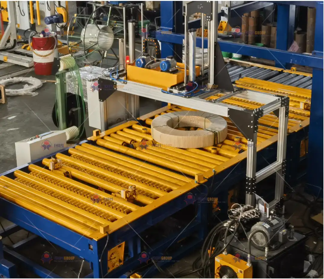
7. Conclusion
When designing and fabricating a coil packing line (encompassing packing, strapping, and stacking equipment), one cannot overstate the importance of methodical material selection. From high-strength steels like Q690D for the machine frameworks to 42CrMo4 for high-speed components, each choice is validated with standardized tests and meticulous simulations. Meanwhile, non-metallic components, such as UHMWPE guide rails and FKM seals, introduce beneficial properties that reduce friction, extend service life, and minimize leakage.
Hydraulic cylinders and pneumatic actuators—vital for secure coil handling—are built around advanced materials like 17-4PH rods and PTFE-aramid fiber composite seals. We also integrate surface modifications such as HVOF spraying and plasma nitriding to effectively combat wear, corrosion, and fatigue. For specialized designs, composites such as CF-PA66 or AlSiC provide remarkable structural and damping advantages, ensuring the equipment remains light, robust, and vibration-resistant.
Finally, the backbone of this entire process is our reliability testing regime and cloud-based materials database. By subjecting components to high-cycle fatigue tests, SEM microscopy, and real-time chemical composition checks, we create a feedback loop that continuously refines the design and material selection. This rigorous approach has yielded substantial increases in the service life of key components, significantly reduced maintenance intervals, and optimized total cost of ownership.
In conclusion, Production Procedure: Material Selection for the Coil Packing Line is not just about picking the toughest steel or the best seal; it’s about orchestrating an integrated approach that addresses structural durability, dynamic response, and cost-efficiency. Our end goal is a highly reliable, safe, and cost-effective packaging solution that meets or exceeds global quality and environmental standards. With this evidence-based, data-driven methodology, we confidently offer equipment that stands up to the toughest conditions while aligning with modern sustainability and lifecycle criteria.
Disclaimer: All technical data, standards, and property values mentioned above are subject to updates and may vary with specific project requirements, regional codes, and manufacturer specifications. For precise engineering design, always reference the most recent versions of ISO, ASTM, DIN, and other relevant standards, as well as the latest engineering reports from your materials supplier.


