Introduction
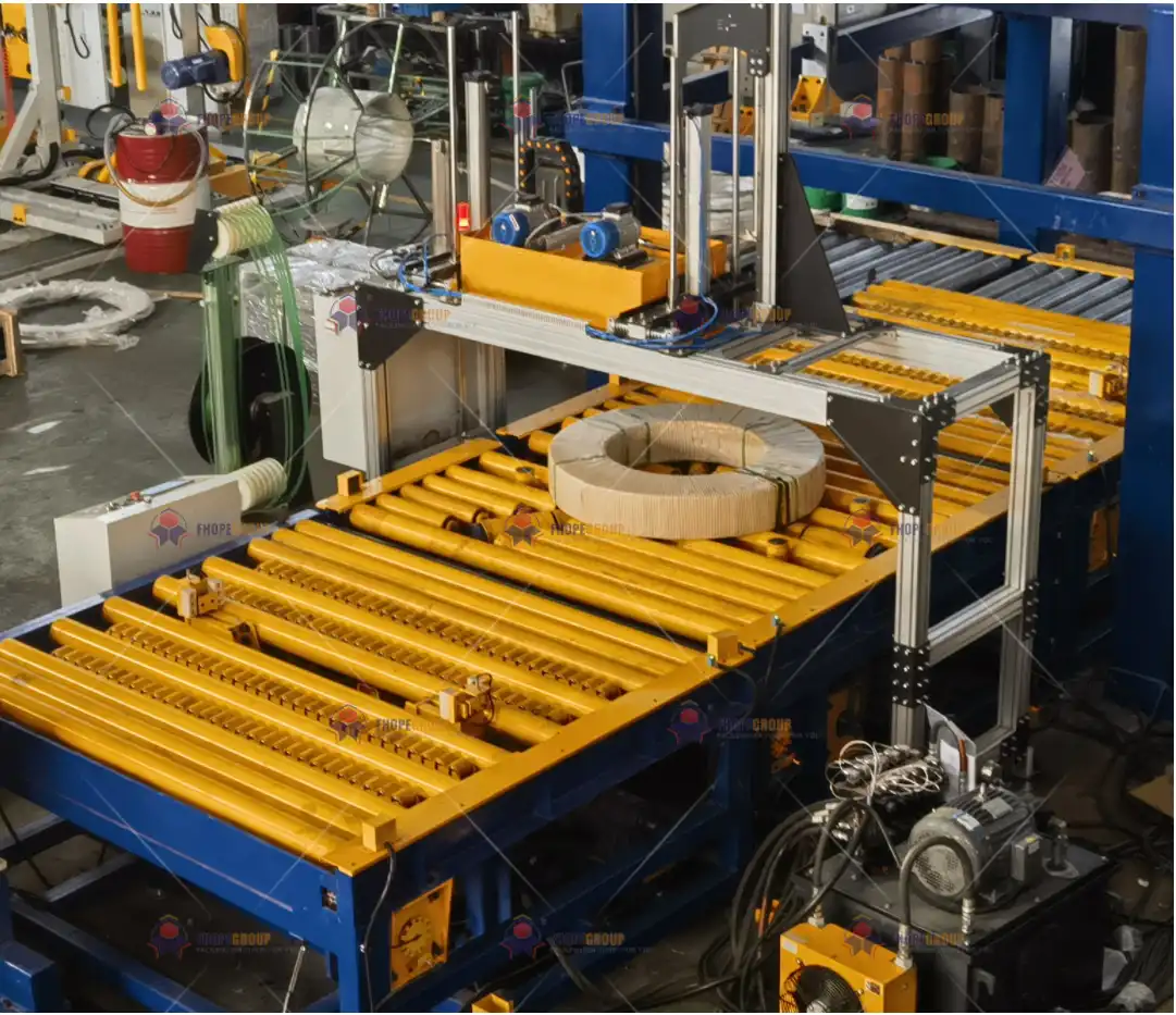
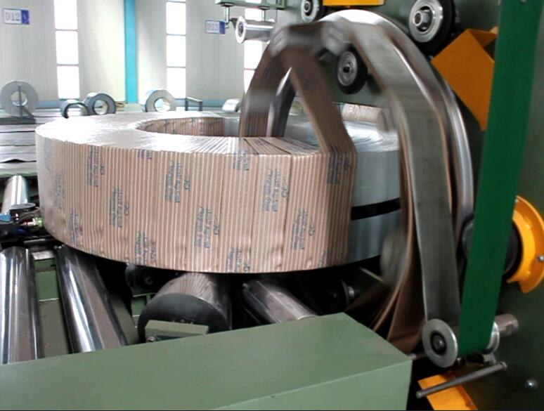
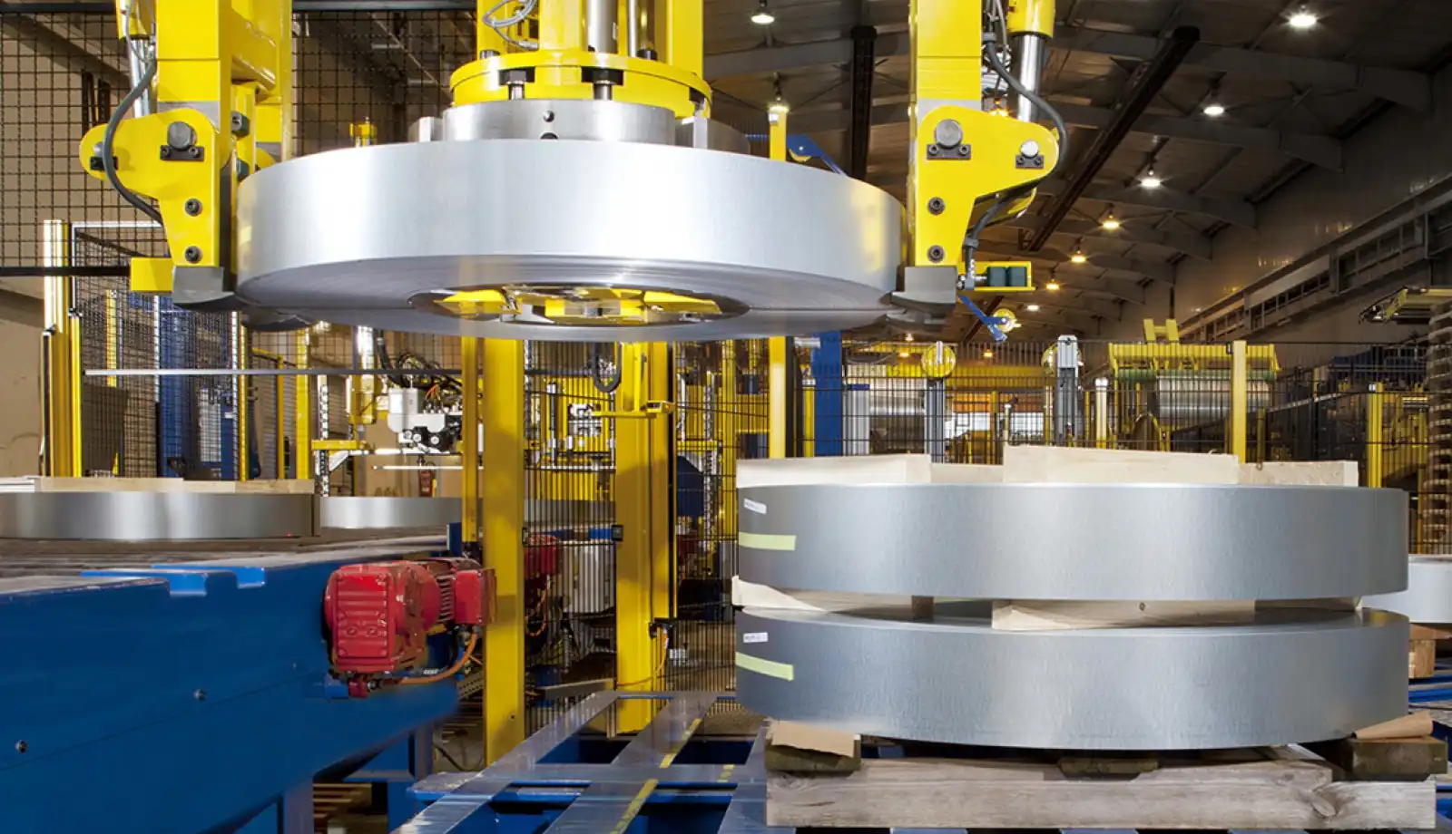
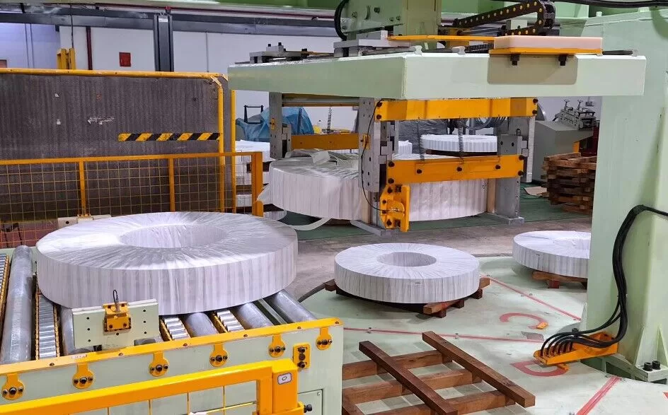
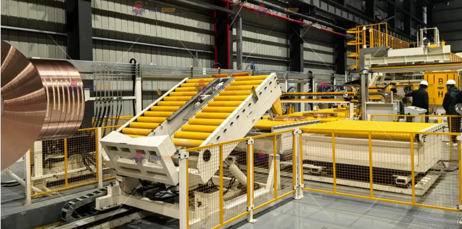
In modern steel service centers and metal-processing plants, coil packing lines (incorporating coil packing machines, coil strapping machines, and coil stacking machines) form a critical link between production and shipping. These systems must withstand high loads, dynamic stresses, corrosive environments, and precise positioning requirements. Alongside conventional structural fabrication and assembly methods, the further processing of the machine’s components—such as quenching, straightening, galvanizing, rubber coating, and painting—significantly enhances durability, performance, and overall reliability.
This article outlines our professional approach to further processing for coil packing line components, reflecting relevant mechanical design norms, manufacturing standards, and quality assurance practices. Emulating the style of The Fabricator, we address each step of the process—from induction hardening to rubber coating—while highlighting how advanced technology and rigorous standards come together to create a finished product capable of delivering exceptional performance.
1. Thermal Chemical Hardening Processes
Steel components in a coil packing line (e.g., rollers, shafts, mandrels, or sliding guides) are often subject to high cyclic loads and contact stresses. In order to ensure their long-term resistance to wear and dimensional stability, we employ a range of heat treatment methods, with a particular emphasis on high-frequency induction hardening. This approach minimizes energy consumption compared to traditional furnace treatments, while allowing precise local hardening.
1.1 High-Frequency Induction Quenching
High-Frequency Induction Quenching involves rapidly heating the target component to a specific austenitizing temperature, followed by a controlled quench. Below is a summary of our key technical specifications and quality criteria:
| Parameter | Technical Specification | Quality Judgment Standard |
|---|---|---|
| Heating Temperature | 860–900 °C (Calculated per material transformation point) | Complete Austenitization (Verified via ASTM E3 Metallography) |
| Quenching Medium | Polymer Aqueous Solution (10% UCON Quenchant A) | Cooling Rate ≥ 80 °C/s (ISO 9950) |
| Hardened Layer Depth | 2–4 mm (Profile Tracking by Magnetic Field Control) | Hardness Gradient ≤ 5 HRC (DIN 50190) |
| Testing Method | Ultrasonic Residual Stress Analysis (ASTM E837 Blind-Hole Method) | Residual Compressive Stress ≥ 300 MPa |
Technical Advantages of Induction Hardening
Precision Control:
Our induction systems utilize FLIR infrared thermography1 in a closed-loop arrangement to maintain the hardening-layer profile. The error in layer depth typically remains within ±0.15 mm, ensuring consistent hardness distribution.Energy Efficiency:
Compared to conventional batch or box furnaces, induction heating can reduce energy consumption by as much as 40%. The formula for energy savings2, ( Q = \Delta T \times m \times C_p \times \eta^{-1} ), highlights how induction rapidly elevates only the surface layer to the required temperature, sparing the entire component from unnecessary thermal soak.Enhanced Mechanical Properties:
Induction-hardened components typically achieve high residual compressive stress3 (≥300 MPa) near the surface, mitigating fatigue crack initiation. This is especially beneficial in critical coil-packing assemblies where repeated impact or rolling contact fatigue may arise.
2. High-Precision Straightening and Forming
The coil packing line contains a variety of metal elements—ranging from guide rails, rails for strapping heads, to framework beams—that must be dimensionally accurate. Even minor deviations in flatness or straightness can compromise machine alignment, leading to premature wear or frequent malfunctions. Thus, precision straightening and forming play a central role in ensuring part reliability.
2.1 CNC Hydraulic Straightening Process
Our typical equipment configuration includes an SMS MEER 9-roll straightening machine integrated with an AI-driven flatness feedback system. Key accuracy indicators are:
- Flatness: ≤ 0.3 mm/m² (ISO 8512 Level A)
- Straightness: ≤ 0.15 mm/2000 mm (EN 10058)
Process Control Methodology
Laser Scanning & Online Contour Monitoring
With a sampling frequency of 1000 Hz, we continuously measure the workpiece shape. The system feeds real-time data into a control loop, adjusting hydraulic forces to correct for any deviations.Elastic-Plastic Deformation Model
We represent total strain as (\varepsilon{total} = \varepsilon{e} + \varepsilon{p}), where (\varepsilon{e}) is the elastic component and (\varepsilon_{p}) is the plastic component. The control system dynamically compensates for springback based on the component’s stiffness and the induced strain, ensuring near-perfect alignment.
2.2 Local Stress Relief Technique
Even after macro-level straightening, residual stresses can persist in localized zones. Such stresses may alter the part’s geometry over time or under temperature variations. To counteract this:
- Method: Local high-frequency vibratory stress relief (15–30 kHz)
- Parameters: Strain amplitude of 0.01%–0.03%, with a treatment duration of 5–8 minutes per meter of material
- Effect: Dimensional stability improvements of ≥60%, verified via 12-cycle thermal cycling tests (ISO 17662)
By applying this localized high-frequency vibration, we relax internal stresses without subjecting the entire component to a second heat treatment, reducing lead times and energy consumption.
3. Core Corrosion Protection Technologies
Coil packing lines may be exposed to moisture, lubricants, acidic cleaning agents, or even marine environments if installed near ports. Corrosion compromises mechanical integrity and can impact the reliability of moving parts. Our strategy revolves around differentiated galvanizing and composite coating systems tailored to the performance requirements and geometry of each component.
3.1 Differentiated Galvanizing Processes
Depending on the size, shape, and intended use of the part, we employ various galvanizing methods:
| Process Type | Application Scenario | Technical Parameter | Corrosion Life (Salt Spray) |
|---|---|---|---|
| Hot-Dip Galvanizing | Heavy-Duty Frames | Zinc Layer Thickness ≥85 μm (ASTM A123) | ~1500 h Before Red Rust |
| Cold Galvanizing | Precision Mechanisms | Zinc-Aluminum Coating ≥20 μm (ISO 1461) | ~800 h Before White Rust |
| Zinc Diffusion | Complex Internal Cavities | Diffusion Layer Depth: 30–50 μm (DIN EN 13811) | ~2000 h With No Base-Metal Corrosion |
- Hot-Dip Galvanizing: Utilized for large frameworks and columns supporting heavy loads. The thicker zinc layer (≥85 μm) offers robust protection.
- Cold Galvanizing: Ideal for slender shafts or linkages where minimal thickness and precise tolerances matter.
- Zinc Diffusion (Sherardizing): Suited for irregular cavities—often found in coil handling or strapping subassemblies—ensuring uniform coverage in areas that are difficult to plate or coat by conventional methods.
3.2 Composite Coating System Design
Beyond galvanizing, we apply advanced paint or polymer-based systems to specific parts that require aesthetic appeal, additional barrier protection, or specialized functional properties (e.g., chemical resistance).
Coating Layer Structure
Chemical Conversion Layer
- Zinc Phosphate film, 2–3 g/m² (ASTM B201)
- Enhances adhesion between the metal substrate and subsequent coatings.
Epoxy Zinc-Rich Primer
- Dry film thickness: ~80 μm
- Adhesion ≥5 MPa (ISO 4624)
- Fills micro-voids and provides a cathodic protective mechanism via zinc particles.
Polyurethane Topcoat
- Self-healing fluorocarbon for enhanced weatherability
- QUV aging resistance ≥6000 h (ISO 11507)
Key Tests
- Impact Resistance: 50 kg·cm (ASTM D2794)
- Chemical Resistance: 48-hour immersion in 5% H₂SO₄ and 10% NaOH with no blistering or coating breakdown (ISO 2812-1)
This multi-layer approach yields excellent barrier properties, preventing moisture and corrosive species from reaching the metal substrate. It also endures mechanical damage better than single-layer coatings, particularly in high-traffic or high-impact areas of the packing line.
4. Functional Surface Treatments
While corrosion protection and dimensional stability are indispensable, some components need additional functional attributes—such as rubber-like cushioning, anti-slip surfaces, or enhanced wear resistance. Two significant technologies used in the coil packing line context are rubber composite coatings and plasma-sprayed ceramic layers.
4.1 Rubber Composite Coating Technology
We frequently apply rubber coatings to rollers, gripping elements, or bumpers that contact the coil edges. This ensures gentle handling, noise reduction, and improved friction control.
| Characteristic | Chloroprene Rubber | Silicone Rubber |
|---|---|---|
| Operating Temperature | −30 °C to 120 °C | −60 °C to 250 °C |
| Adhesion | ≥4.5 MPa (ASTM D429, Method B) | ≥3.8 MPa (Requires Specialized Primer) |
| Abrasion Resistance | DIN Abrasion <80 mm³ | DIN Abrasion <50 mm³ |
| Special Feature | Oil Swell <5% (ASTM D471) | Water Contact Angle >150° (Nanomodified Superhydrophobicity) |
- Chloroprene (Neoprene): Preferred for moderate temperature ranges and exposure to oils/lubricants.
- Silicone Rubber: Useful in high-temperature environments or where hydrophobic (water-repellent) surfaces are desired, reducing contamination buildup.
4.2 Plasma Sprayed Ceramic Coatings
For components subject to extreme friction, high temperature, or abrasive media, ceramic coatings outperform metals and conventional paints. We primarily use Al₂O₃–13%TiO₂ nano-agglomerated feedstock under an Ar/H₂ plasma environment.
- Power: ~40 kW
- Deposition Efficiency: 65%–70%
- Porosity: <2% (post-sealing)
- Microhardness: ≥1100 HV0.3
Performance Benefits:
- Enhanced Wear Resistance: Ceramic layers can increase service life by 3 to 5 times, especially in regions of sliding contact.
- Erosion and Cavitation Resistance: Verified by ASTM G32 testing, these coatings show up to a 10-fold improvement in cavitation erosion resistance.
- Thermal Barrier: The low thermal conductivity of ceramic helps shield underlying metal from rapid temperature fluctuations.
5. Quality Assurance System
Achieving the desired performance of a coil packing line requires not only thorough design and specialized processes but also robust quality verification. We employ both laboratory-based and in-situ testing methods to confirm that each finished component aligns with stringent mechanical, chemical, and environmental standards.
5.1 Accelerated Corrosion Testing Matrix
Given corrosion is a leading cause of unplanned downtime, we replicate harsh service conditions through a variety of accelerated tests:
| Test Method | Simulated Environment | Acceptance Criteria |
|---|---|---|
| Neutral Salt Spray | 5% NaCl, 35 °C Continuous Spray | Red Rust Formation > 2000 h (ASTM B117) |
| Cyclic Corrosion | GMW14872, 80 Cycles | Corrosion Creep ≤ 2 mm (VDA 621-415) |
| Industrial Atmosphere Exposure | Marine Platform Field Coupons | Annual Corrosion Rate <6 μm (ISO 9223, Category C5-M) |
- Neutral Salt Spray (ASTM B117): A standard reference test to compare different coating performance; we aim for ≥2000 hours of red rust-free exposure for critical frames.
- Cyclic Corrosion (GMW14872): Repetitive cycles of salt spray, humidity, and drying mimic real-world conditions.
- Field Exposure: For certain product lines, we place test coupons in actual marine or industrial sites, verifying real-time performance over a designated period.
5.2 Functional Testing Platform
Beyond corrosion, our further processing steps must also pass mechanical and functional verifications:
- Tribology: Ball-on-disk test (sliding speed of 0.5 m/s, 50 N load) measures friction coefficient and wear rates under lab-controlled conditions.
- Thermal Shock: –40 °C to +150 °C, 30 cycles (DIN EN 13523-13) to detect any coating delamination.
- Electrochemical Analysis: Potentiodynamic polarization (measuring pitting potential (E_b \ge +320) mV SCE) to gauge the coating’s ability to resist localized corrosion.
By employing these tests, we ensure that each batch of galvanized, painted, or rubber-coated parts meets the real-world demands of the coil packing line environment.
6. Techno-Economic Comparison
From initial capital expenditures to long-term maintenance and environmental compliance, the chosen processing methods substantially influence overall costs. Below is a concise comparison of a traditional process versus our enhanced solutions:
| Technical Dimension | Traditional Approach | Our Optimized Approach | Benefit |
|---|---|---|---|
| Life-Cycle Cost | ~1.8 RMB/hour·m² | ~1.2 RMB/hour·m² | 33% Reduction |
| Maintenance Interval | ~12 Months | ~36 Months | 3× Extension |
| Corrosion Resistance | ISO 12944 C4 | Exceeding C5-M Classification | Enhanced Service Range |
| Surface Treatment Speed | ~2.5 m²/h | ~4.8 m²/h (Robotic Spraying) | 92% Efficiency Gain |
- Life-Cycle Cost: Our advanced coating and hardening techniques reduce the frequency of part replacement, saving labor and downtime costs.
- Maintenance Interval: Extended from 12 months to 36 months, thanks to improved corrosion resistance and wear characteristics.
- Corrosion Rating: Upgraded beyond ISO 12944 C4 to near C5-M performance, suitable for aggressive marine and industrial atmospheres.
- Process Throughput: By integrating robotic spraying and automated monitoring, we nearly double surface treatment speeds, expediting project schedules.
7. Visualization and Data Traceability
Given the complexity of modern manufacturing and finishing processes, we employ a range of visual and data-driven tools to communicate results clearly and maintain full traceability:
- Coating Cross-Section via Electron Microscopy
Showcases the bonding interface between zinc-rich primer and polyurethane topcoat. - Accelerated Corrosion Panels
Lined up in a chronological sequence to illustrate the timeline of rust or blister formation. - Thermographic Imaging of the Straightening Process
Dynamic feedback loops correlate with roller pressures and temperature gradients. - 3D Surface Roughness Maps
Demonstrating the improvement in surface topography before and after polishing or sealing (measured in Sa, Sz parameters).
We also attach individual QR codes to each workpiece, binding all relevant process parameters—heat treatment cycles, coating thickness measurements, batch numbers—to a centralized digital system. This ensures that every component used in the coil packing line has a complete manufacturing and test history.

8. Conclusion
The further processing stage for coil packing line components is a keystone in elevating the system’s overall performance, reliability, and longevity. By integrating high-frequency induction hardening, precise hydraulic straightening, stress relief methods, differentiated galvanizing, multi-layer coatings, and functional treatments (rubber or ceramic), we endow the packing machines, strapping machines, and stacking devices with enhanced structural resilience and corrosion defense.
Simultaneously, extensive quality testing—ranging from accelerated corrosion chambers to real-time tribological evaluations—verifies that our process innovations deliver tangible improvements in cost-efficiency, extended service intervals, and environmental adaptability. Real-world data show that these advanced finishing methods can reduce life-cycle costs by over 30%, while mitigating downtime through prolonged maintenance intervals.
Looking ahead, the expanding demand for high-integrity coil handling equipment—capable of withstanding more aggressive conditions with minimal intervention—will continue to push manufacturers toward advanced materials, processes, and testing protocols. By staying at the forefront of coating innovation, surface engineering, and digital traceability, we ensure that coil packing lines not only meet current industry standards but also remain robustly prepared for future challenges.
In essence, the synergy of mechanical design best practices, modern finishing processes, and rigorous validation forms the backbone of a reliable, long-lasting coil packing line. Whether dealing with the extremes of marine atmospheres or the routine demands of an industrial warehouse, these meticulously processed components uphold The Fabricator’s central tenet: durable and precise workmanship that delivers consistent results day after day.
Explore this link to understand how FLIR infrared thermography enhances precision in induction heating processes. ↩
Discover the science behind energy savings in induction heating and its impact on efficiency and cost reduction. ↩
Learn about the advantages of high residual compressive stress in improving the durability and performance of components. ↩