In today’s metal fabrication landscape, coil packing lines need to balance engineering precision, flexibility, and safety. Whether your shop is packaging steel coils for long-haul transport or short-term storage, the underlying principles remain the same: robust design, validated performance, and a holistic view of mechanical, electrical, and human factors. This article focuses on how a typical design and engineering process unfolds for a coil packing line, from receiving initial customer requirements to delivering a fully verified solution. Throughout, we’ll address 1:1 scale 3D modeling, finite element analysis (FEA), and the integration of standardized modules that expedite the path from concept to production.

1. Design Stages and Inputs
1.1 Requirements Translation Matrix
A well-structured project begins by translating customer specifications—such as throughput, coil size, and safety guidelines—into mathematical engineering models. For instance, the wrapping speed can be expressed as:
Wrapping Speed = f(Coil Diameter, PE Film Thickness, Pre-Stretch Ratio)
This formula captures the coil’s diameter range and the film’s technical properties. If a customer mandates a specific pre-stretch ratio or film thickness, the function constrains the system’s wrapping velocity and torque requirements. The ultimate goal is to ensure consistent tension and coverage without compromising speed or overloading motors.
Beyond performance metrics, boundary conditions—like building clearance or floor loading capacity—factor into the system’s final shape. For example, if a facility has tight ceiling height, mechanical designers incorporate lower-profile components and verify clearances in 3D layouts. These boundary constraints directly influence the mechanical footprint and may require alternative solutions, such as built-in coil ramps or modular strapping heads.
1.2 Standardized Design Tiers
To improve engineering efficiency while maintaining flexibility for custom needs, we often employ a tiered approach:
- 60% Common Modules: Based on ISO 12100 safety standards and universal mechanical subassemblies (e.g., conveyor frames, standard tensioner mechanisms).
- 30% Configurable Components: Servo motor sizes or drive power ratings can vary, but the core design remains consistent.
- 10% Custom Development: Specialized needs such as anti-corrosion or salt-fog-resistant packaging for maritime shipments might call for unique film-handling subassemblies or protective enclosures.
This strategy allows the engineering team to reuse proven modules, minimize design errors, and accelerate project timelines, all while preserving enough room for unique customer requirements.

2. Key Subsystem Engineering Design
2.1 Coil Packing Machine Core Mechanisms
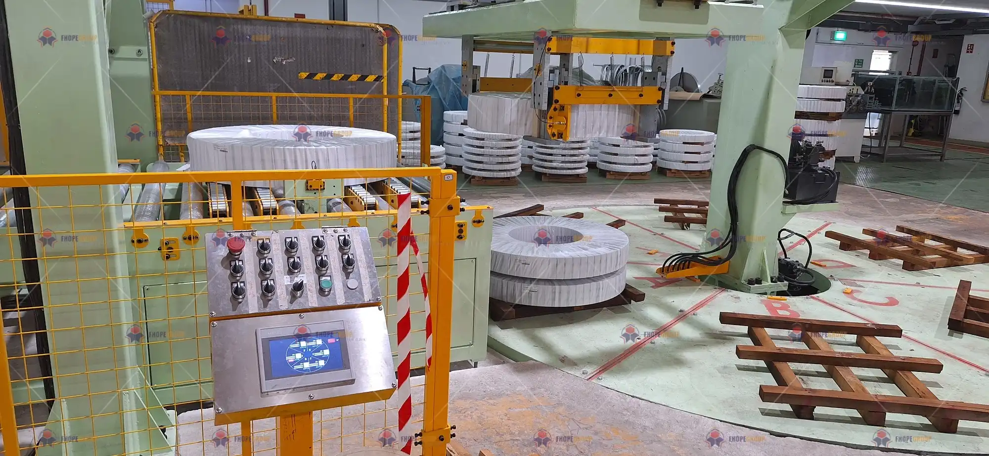
At the heart of any packing line is the coil packaging machine. This station typically wraps each coil in layers of PE film, VCI paper, or other protective materials.
Adaptive Diameter Adjustment
Modern packing lines handle coils ranging from 500 mm up to 2000 mm in diameter. An adaptive cradle or ring system, guided by sensors, identifies coil dimensions on the fly. Designers often verify the contact forces in gear drives using Hertzian contact stress calculations to ensure stable motion and minimal wear.Planetary Gear Torque Distribution
High-load wrapping rings leverage planetary gear sets to distribute torque efficiently. Calculation includes verifying gear tooth contact patterns and ensuring gear materials meet or exceed the required hardness (e.g., surface hardness HRC58+ for load-intensive situations).Ultrasonic Sensor Selection
Ultrasonic sensors with a 2 mm resolution at a 2000 mm range help detect coil dimensions accurately. Selecting an appropriate sensor ensures stable feedback loops for tension control and coil positioning.Film Tension Control Model
A crucial factor in consistent wrapping is controlling the film’s tension across the coil’s circumference. A common tension model is:
T(z) = T0 × e^(μθ)
where T0 is the initial tension, μ is the friction coefficient, and θ is the wrap angle. Designers often implement a dual closed-loop system—speed loop (±0.5% accuracy) plus tension loop (±2 N accuracy)—to maintain the ideal film stretch without tearing or slack.
2.2 Fully Automatic Strapping System
Once the coil is wrapped, strapping adds reinforcement. The strapping machine’s design entails geometric path modeling and 3D kinematic solutions (e.g., Denavit-Hartenberg parameterization) to guide the strapping head around the coil.
Geometric Path and Clearance
The 3D model verifies that the strapping head can reach all necessary points without interference. A typical safety clearance is set at ≥15 mm, enforced by laser scanning systems (like SICK scanners) that halt motion if an unexpected obstruction enters the work zone.Hot-Melt or Heat-Seal Joint
Many lines use heat-seal or friction-weld heads for plastic straps. The process window might be:
| Parameter | Allowed Range | Monitoring Method |
|---|---|---|
| Heating Temp | 360 ± 10 °C | Infrared Thermal Imager |
| Holding Time | 1.2 – 1.8 s | High-Speed Digital Timer |
Deviations from these ranges can weaken or overheat the strap. Automated systems thus monitor temperature in real time, ensuring consistent bond strength.
2.3 Intelligent Stacking System
After strapping, coils are either moved onto pallets or stacked in dedicated racks.
Pose Estimation Algorithms
If an overhead robot or multi-axis manipulator is used, the system may rely on homogeneous transformation matrices to define the coil’s exact position and orientation. Calibration of the tool center point (TCP) ensures minimal deviations when stacking heavy coils.Collision Avoidance
In advanced installations, the robot’s motion planning checks bounding boxes in real time (often coded in a language like RAPID or KRL). This safeguard prevents damaging collisions with adjacent coils or structural pillars.Hydraulic Synchronization
For vertical lifts, hydraulic cylinders sometimes operate in tandem. A flow-matching equation,
Q1/A1 = Q2/A2
helps maintain synchronized movement. Cross-coupling compensation, with ±1% droop characteristic, ensures both cylinders raise or lower the load evenly. This helps prevent coil shifting or tipping on the platform.
3. Cross-Disciplinary Integrated Design
3.1 Mechatronic Solutions
With coil weights often exceeding several tons, servo motors and hydraulic drives must be carefully matched to the load’s inertia. A standard rule:
Motor Inertia / Load Inertia = 1/3 ~ 1
guides selection to keep servo performance stable and avoid overshoot or sluggish response. Meanwhile, pressure pulsations in hydraulic lines can be dampened via accumulators; a rough volumetric formula is:
V0 = ΔV / (1 - (P1/P2)^(1/1.4))
where ΔV is the net fluid volume change and (P1/P2) represents pressure ratios.
3.2 Fault Tree Analysis (FTA)
Reliability is vital in heavy machinery. An example top event is film breakage during wrapping. An FTA might reveal:
TOP Event: Film Breakage ├─ Mechanical Factors (40%) │ ├─ Eccentric Guide Roller (Detected by Laser Alignment) │ └─ Pre-Stretch Roller Hardness < Spec (HRC58-62 required) └─ Control Factors (60%) ├─ Tension Setpoint Error (±5 N closed-loop correction) └─ Missing Velocity Feedforward (Add Acceleration Compensation)
From this, the design team can assign mitigation measures, such as specifying higher roller hardness, implementing tension sensors, or refining servo feedforward parameters.
3.3 Ergonomics and Operator Safety
Even a highly automated line requires manual intervention for routine checks or maintenance. EN ISO 13857-2008 recommends minimum clearance for safe human access:
| Operation | Minimum Clearance |
|---|---|
| Tool Change Areas | 600 mm |
| Electrical Cabinet Doors | 1200 mm |
These guidelines reduce the risk of pinch points and allow operators to quickly access equipment without contorting in unsafe positions.

4. Digital Design Toolchain
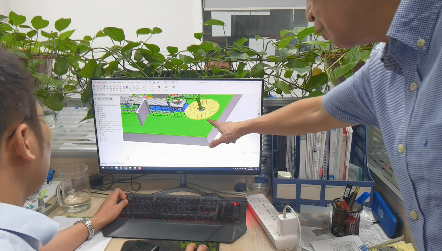
4.1 3D Modeling and Simulation
A robust digital workflow leverages parametric modeling in SolidWorks or similar CAD tools. Standardized hardware—like bearings, fasteners, or couplings—should comprise at least 85% of the total parts library. This approach:
- Accelerates BOM Generation: Automated item tracking ensures consistent part numbering.
- Supports FEA: ANSYS helps run transient dynamic analyses, verifying that maximum stress remains below ~240 MPa at 30 Hz vibration frequencies.
These simulations are especially critical for high-speed wrapping rings, stacker arms, or rotating conveyors where dynamic loads spike during sudden stops or starts.
4.2 Control Logic Virtual Commissioning
Siemens NX Mechatronics Concept Designer or related platforms facilitate virtual commissioning. In a virtual environment, the design team can:
- Map Virtual Axes: Test multi-axis synchronization without risking physical collisions.
- Signal Response Timeline: Validate that sensor inputs and drive outputs match expected timing, with a target rise time under 5 ms.
- Emulate Production Cycles: By simulating coil load-unload sequences, the software highlights potential misalignments or waiting states in the PLC logic.
4.3 BOM and Documentation Management
Once mechanical and electrical designs mature, EPLAN or equivalent tools unify hardware, harness, and panel layouts. Many solutions now integrate direct manufacturer APIs for sourcing drives (e.g., Mitsubishi, Bosch Rexroth). The result is a live BOM, automatically updated with any design modification. That synergy saves hours of manual cross-referencing and reduces the chance of mismatch between mechanical CAD, electrical schematics, and purchase orders.

5. Engineering Validation Workflow
5.1 Design Review Milestones
| Phase | Review Focus | Acceptance Tool |
|---|---|---|
| Concept Review | Functional Coverage | Requirement Traceability Matrix |
| Detailed Design Review | Tolerance Stack Analysis | CETOL 6σ |
| Pre-Shipment Review | EMC Compliance Tests | 3 m Anechoic Chamber Data |
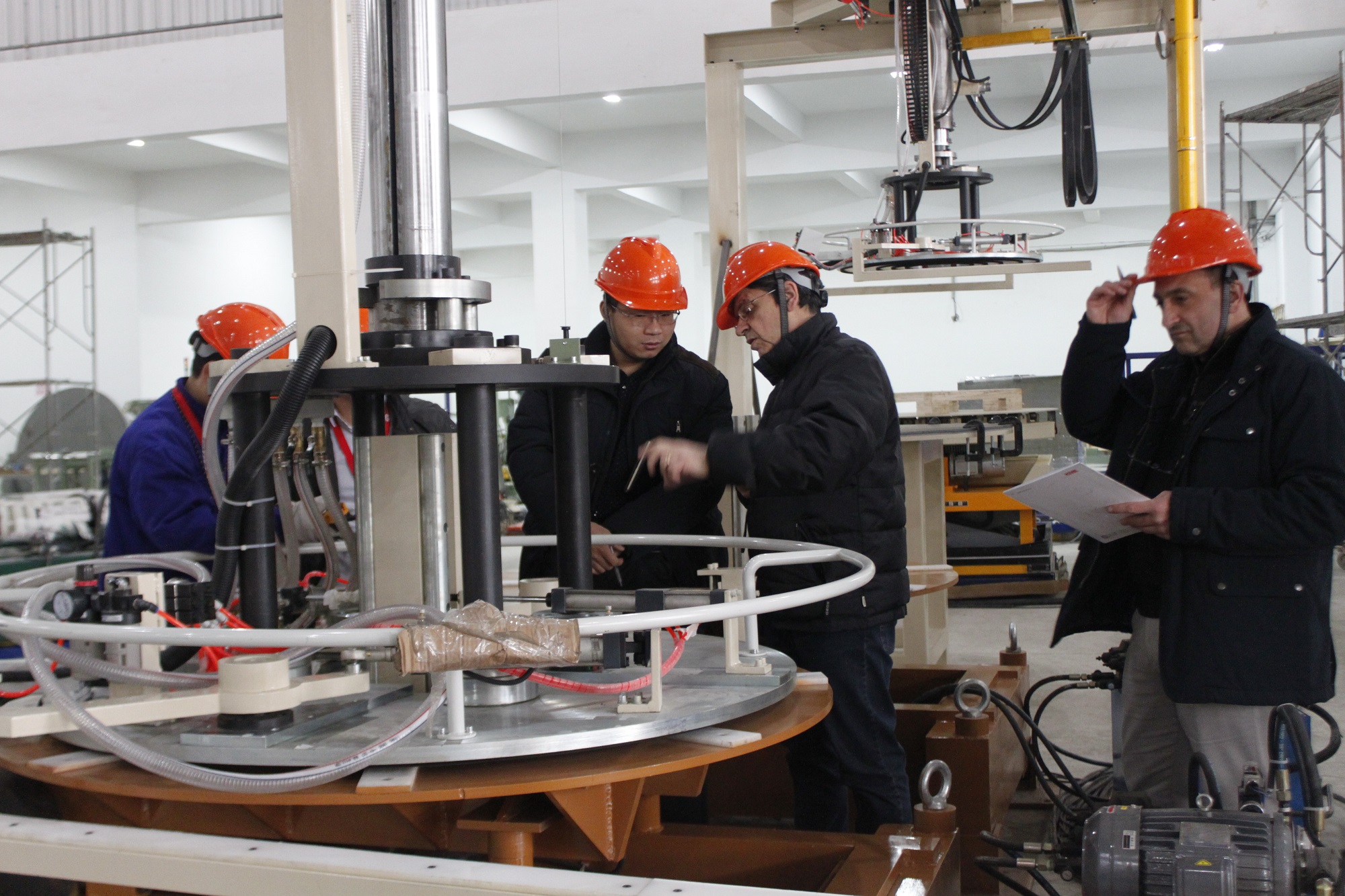
- Concept Review: Ensures the system covers all major requirements, from coil dimension ranges to required throughput.
- Detailed Design Review: Tolerance stack-up is checked thoroughly, especially where multiple subassemblies join (like wrapping arm + bearing + tension roller).
- Pre-Shipment: In-depth functional checks confirm electromagnetic compatibility (EMC) for VFDs, servo drives, and PLC-based control panels.
5.2 Prototype Test Protocol
Real-world tests complement digital simulations:
Accelerated Life Testing
Machines run 3× the normal load (within safe limits) for up to 8 hours to identify early wear points. Components like bearings or belts that fail early can be redesigned or replaced before final deployment.CPK Analysis for Packaging Accuracy
Process capability (CPK ≥ 1.67) indicates a stable operation. Wrapping or strapping inconsistencies—such as slack film or misaligned straps—are measured using high-resolution sensors, then analyzed statistically.Energy Consumption Measurement
High-precision power meters (e.g., HIOKI PW3390) log energy profiles over extended runs. If the data surpasses customer targets, design optimizations (like improved VFD parameters or servo dwell logic) may be introduced to reduce consumption.

6. Engineering Deliverables
Mechanical Documentation
- Overall GA (General Assembly) Drawings: Following ISO 128-40 for dimensioning and tolerance annotations.
- Hydraulic Circuit Diagrams: Conforming to CETOP symbol standards, specifying flow control valves, pressure relief valves, and accumulator placements.
Electrical Documentation
- Control Cabinet Layout: Certified to IP54 or higher if the environment involves moisture or dust. The panel arrangement must pass relevant short-circuit and thermal tests.
- PLC Program Architecture: Written per IEC 61131-3 guidelines, often mixing ladder logic and function blocks for advanced servo or tension loops.
Digital Handovers
- JT Lightweight 3D Models: Include PMI (Product Manufacturing Information) for reference without sharing proprietary CAD details.
- XML Signal Mapping: Lists every I/O point (sensors, motors, safeties) in a standardized data exchange format for easy integration into a plant-wide SCADA or MES system.
7. Technology Advantages Comparison
To highlight how advanced engineering methods outperform typical solutions, a concise table helps prospective clients weigh the benefits:
| Dimension | Conventional System | Our Engineered Solution |
|---|---|---|
| Changeover Time | 45–60 min | ≤20 min (Quick-Change Module Patent) |
| Energy Utilization | ~72% | ~89% (Accumulator & VFD Optimization) |
| Design Change Response | ~72 hours | ~8 hours (Parametric Model Updates) |
- Quick-Change Modules
Innovations in mechanical design let operators swap film rolls or strapping heads without needing extensive re-calibration. - Improved Energy Efficiency
Combining advanced accumulator-based hydraulic systems with fine-tuned VFD parameters raises overall energy utilization from an industry average of ~72% to nearly 89%. - Rapid Design Updates
Parametric 3D modeling ensures that a coil diameter shift from 1000 mm to 1200 mm automatically updates the supporting subassemblies, drastically cutting re-engineering hours.

Supporting Visuals and Conclusion
While words and tables lay out the technical scope, integrating clear visuals substantially increases stakeholder confidence. Examples include:
- 3D Exploded View Animations: Show how main assemblies—wrapping ring, tension roller, motor bracket—fit together, aiding in maintenance training.
- Stress Contour Comparisons: Displaying “before” and “after” results of topology optimization helps justify material choices.
- Control Sequence Waveforms: Illustrate multi-axis synchronization and rapid e-stop response in real-time waveforms.
- High-Speed Camera Footage: Captures dynamic phenomena like film stretching or strapping head movement at critical moments.
Ultimately, Design and Engineering is about ensuring every nut, bolt, sensor, and line of PLC code works in harmony. By combining best-in-class mechanical approaches, rigorous FEA validation, and advanced control logic, fabricators can deliver a coil packing line that’s efficient, reliable, and easier to maintain. The synergy of standardized modules, parametric designs, and robust testing protocols reduces technical risk and drives down total cost of ownership.
From concept reviews to prototype trials, and from mechanical drawings to a virtual twin, each stage in the process helps refine and validate the final product. With these thorough design and engineering strategies, coil packing lines can adapt swiftly to evolving client demands, maintain competitive production speeds, and exemplify the forward-thinking spirit of modern fabrication shops.
[1]
Understanding the formula for Wrapping Speed is crucial for optimizing packaging processes and ensuring efficiency in engineering designs.
[2]
Exploring boundary conditions will provide insights into how design constraints shape engineering solutions and improve project outcomes.
[3]
Learning about mechanical footprint factors can help in creating efficient designs that meet space and performance requirements.