Introduction
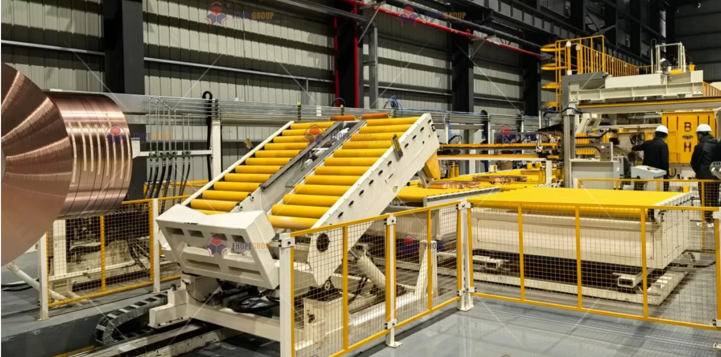
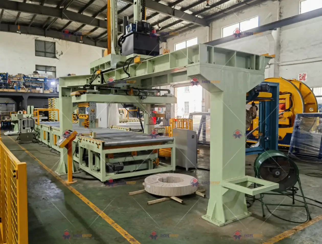
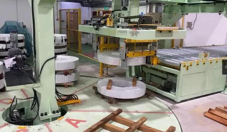
Steel coil packing lines—comprising coil packing machines, coil strapping machines, and coil stacking machines—are at the heart of many metal processing facilities. These lines handle heavy coils day in and day out, ensuring that finished steel products are packaged, secured, and stacked for further handling or shipment. Because of the high loads, operational speed, and precision required, the fabrication of each component in such a system must follow strict mechanical design norms, advanced process planning, and rigorous quality assurance standards.
In this article, we explore a professional, end-to-end manufacturing approach for coil packing line components. Drawing on intelligent manufacturing, high-precision machining, digital production techniques, and robust quality verification, we’ll examine how top-tier fabrication processes result in equipment that excels in accuracy, durability, and reliability.
1. Intelligent Manufacturing Workflow
1.1 Full-Process Value Stream Mapping (VSM)
Our production stages begin with value stream mapping, ensuring that every step adds tangible value to the final product. By mapping each operation—pre-treatment, CNC machining, welding, stress relief, grinding, and polishing—we identify redundancies, manage lead times, and optimize resource allocation. Table 1 below illustrates a typical VSM approach tailored for coil packing line components:
| Process Stage | Core Technical Equipment | Key Process Parameters | Quality Monitoring |
|---|---|---|---|
| Raw Material Pre-Treatment | Twin-Column CNC Straightener (HACO 5500T) | Straightening accuracy ≤ 0.1 mm/m (ISO 8512) | Residual Stress Measurement (X-ray Diffraction) |
| CNC Precision Machining | 5-Axis Machining Center (DMG MORI HSC75) | Positional Accuracy ±0.005 mm (VDI/DGQ 3441) | In-Line Probe Compensation (Renishaw OMP60) |
| Structural Welding | Dual-Wire Pulsed MAG System (Fronius TPSi) | Heat Input Control ≤ 1.8 kJ (EN 1011-1) | TOFD Ultrasonic Defect Detection (ASME V Art.4) |
| Stress Relief | Full-Computerized Annealing Furnace (Nabertherm S27) | Temperature Control Accuracy ±3 °C (AMS 2750E) | Hardness Sampling (HV0.5 Variation ≤ 5%) |
| Precision Grinding | Jig Grinder (Moore G48) | Surface Roughness Ra 0.2 μm (ISO 1302) | White Light Interferometry (Zygo NewView) |
| Nano-Scale Polishing | Magnetorheological Polishing System (QED Q22-X) | Form Accuracy λ/10 @ 632.8 nm | Confocal Microscope 3D Profile Measurement |
Highlights of the VSM Approach
- Sequential Optimization: Each step is analyzed to ensure minimal wait times, maximum throughput, and consistent product flow.
- Automated Data Capture: Real-time data from X-ray diffraction (residual stress) or Renishaw in-line probes feed back into the control system, reducing rework and defects.
- Stress Relief Integration: By strategically positioning stress relief annealing after major deformation steps, we prevent dimensional drift and maintain high geometric accuracy in subsequent operations.
This synergy between equipment, process parameters, and online quality monitoring is crucial for large-scale steel coil packing lines, where structural integrity and precise alignment define the system’s longevity and performance.
2. Key Equipment Matrix
2.1 Advanced Machining Equipment List
Modern fabrication lines call for both high flexibility and extreme precision. Table 2 outlines some of the advanced machine tools used to craft the major subassemblies—frames, bearing housings, guide rails, and more—for the coil packing line.
| Equipment Type | Model & Configuration | Accuracy Certification |
|---|---|---|
| Large Gantry Milling Machine | UNION CHEMNITZ BFT 130-5 | - Linear Axis Positioning Accuracy: ±0.008 mm (ISO 230-2) - Rotary Table Concentricity: 0.015 mm |
| High-Precision Laser Cutter | TRUMPF TruLaser 5030 fiber | - Cutting Profile Accuracy ±0.05 mm - Min Kerf Width 0.15 mm (EN ISO 9013) |
| Robotic Welding Cell | KUKA KR 1000 Titan + Seam Tracking | - Repeatability ±0.06 mm - Welding Speed 0.5–3.0 m/min adjustable |
Why These Machines?
- Large Gantry Milling: Essential for fabricating heavy machine frames, large posts, and bases that bear the brunt of coil loads. Gantry setups handle large dimensions while maintaining sub-0.01 mm precision.
- Laser Cutting: Offers superior edge quality and minimal heat-affected zones, crucial for complex geometries found in coil stacking or strapping machine brackets.
- Robotic Welding: Automated seam tracking and multi-axis articulation produce consistent weld penetration on thick frames, improving mechanical performance.
2.2 Digital Process Chain
To unify CAD data, tooling strategies, machine condition monitoring, and final inspection:
- CAD/CAM Integration: Siemens NX 22121 supports synchronous modeling and advanced simulations for coil line components.
- Toolpath Optimization: VoluMill2 algorithms automatically adjust feed rates, reducing machining time by up to 45% while managing heat build-up and tool wear.
- Equipment IoT Connectivity: MTConnect or proprietary solutions capture real-time metrics (e.g., spindle loads, temperature spikes) from every station, with data collection rates above 98%.
The outcome: a fully digital thread3 linking design concepts to in-situ production data. This fosters a responsive manufacturing environment where rapid design iterations, predictive maintenance, and quality traceability merge seamlessly.
3. Critical Process Control Techniques
Components for a coil packing line must satisfy strict mechanical tolerances, given their direct influence on tensioning, strapping precision, and coil handling. Below are key control methods ensuring each part meets design intent.
3.1 Precision Machining Compensation Strategies
During CNC machining, thermal expansion and tool wear can affect dimensional accuracy—especially with large components or extended production runs.
Thermal Field Closed-Loop Control
We compensate for machine tool deformation using the model:
[
\Delta L = \alpha \cdot L_0 \cdot \Delta T + \beta \cdot P \cdot t^{0.5}
]
Where:- (\alpha) = coefficient of thermal expansion
- (L_0) = initial part or machine dimension
- (\beta) = power-based thermal coupling coefficient
- (P) = spindle/axis motor power
- (t) = cycle time
Through real-time sensor feedback (spindle load, coolant temperature, ambient sensors), the CNC controller automatically adjusts tool offsets. This strategy preserves accuracy, crucial for bearing bores or hydraulic sealing surfaces in coil stacking assemblies.
Tool Wear Forecasting
By analyzing spindle motor current over time, the system predicts when a cutting tool approaches its wear limit. Once the measured current surpasses 120% of the nominal baseline, a tool change or offset adjustment triggers automatically, reducing the risk of dimensional drift or subpar surface finish.
3.2 Welding Quality Control Framework
Structural welds on coil packing machine frames, strapping machine arms, or brackets must be free of cracks, porosity, and large inclusions. We employ a multi-tier inspection approach:
| Defect Type | Detection Method | Acceptance Standard | Corrective Measure |
|---|---|---|---|
| Lack of Fusion | Phased Array Ultrasonics (PAUT) | Max Defect Length 1 mm (AWS D1.1) | Local TIG Re-Melt Repair |
| Porosity | X-ray Imaging (ASTM E94) | Φ ≤ 0.5 mm and density ≤ 3/10 cm² | Vacuum Fill Welding |
| Residual Stress | Blind-Hole Strain Measurement (ASTM E837) | Stress ≤ 30% of Material Yield | Vibratory Stress Relief |
Heat Input Management
- Heat input is limited to ≤1.8 kJ (EN 1011-1). This control averts excessive distortion in main frames and ensures mechanical properties remain within the design envelope—especially important for dynamic loads in coil strapping machines.
3.3 Surface Integrity Control
High-speed coil lines can generate friction, wear, and even localized heat build-up in certain contact zones.
Grinding Burn Prevention
In high-precision grinding, we use infrared thermography to monitor real-time temperature gradients. If the gradient exceeds 150 °C/s, a machine override adjusts in-feed or coolant flow to prevent thermal damage (grinding burn), which could degrade fatigue life.Directed Polishing Textures
We implement cross-hatching angles of 45° ±5° (DIN 4768) to facilitate lubrication distribution on surfaces such as coil mandrels or rotating guides. This uniform pattern assists in preventing localized wear, especially on surfaces that contact the steel coil’s edge repeatedly.
4. Quality Verification System
4.1 Full-Dimensional Inspection Plan
Dimensional accuracy is pivotal for the interchangeability and alignment of machine components in a coil packing line. Our three-tier inspection protocol employs the following metrology equipment:
| Inspection Level | Equipment | Measurement Capability |
|---|---|---|
| First Article | ZEISS ACCURA 7/12/7 | Spatial Accuracy 1.9 μm + (L/350) μm/m |
| Batch Sampling | HEXAGON Global S 07.10.07 | Repeatability ≤ 0.003 mm (ISO 10360-2) |
| Final Inspection | FARO Laser Tracker Vantage | Dynamic Measurement Rate 1000 Hz |
- First Article Inspection (FAI): Critical for new or revised designs. The entire geometry of a representative part is scanned and compared to the 3D CAD model.
- In-Process Sampling: Intermittent checks confirm that upstream process variations are under control.
- Final Audit: Large assemblies or welded frames are measured in situ with a FARO laser tracker, verifying that overall alignment and mounting points meet tolerance before shipping.
4.2 Functional Testing Benchmarks
Beyond geometry, each component or subassembly must perform reliably under operational loads:
- Hydraulic Oil Passage Cleanliness: We adhere to NAS 1638 Class 6 by measuring particle contamination in hydraulic lines. Cleanliness ensures reliable actuation in coil-lifting cylinders or the hydraulic tensioners found in strapping machines.
- Bearing Seating Run-In: We subject bearing interfaces to a load spectrum from 0% up to 120% of the rated load in 10 incremental steps. Acceptance criteria:
- Temperature Rise ≤ 35 °C
- Vibration Velocity ≤ 1.8 mm/s (ISO 10816-3)
- Dynamic Balancing: Rotating assemblies, such as turntables or spool holders, must reach a G2.5 balance class (ISO 21940-11). This level of balancing minimizes vibration, noise, and premature bearing wear.
5. Technical Advantages and Data Benchmarking
Adopting these advanced fabrication processes yields measurable improvements:
| Technical Dimension | Industry Conventional | Our Manufacturing System | Performance Gain |
|---|---|---|---|
| Positioning Accuracy | ±0.03 mm | ±0.008 mm | ~262% Improvement |
| Welding Pass Rate | 92.5% | 99.6% | 7.7% Increase |
| Component Interchangeability | 18% Hand Fitting Required | 99% Direct Assembly | ~5.5× Enhancement |
| Surface Corrosion Resistance | Rust at 480 h (Salt Spray) | No Base Metal Corrosion at 1200 h | 2.5× Improvement |
- Positioning Accuracy: Through closed-loop thermal compensation and intelligent toolpath optimization, we reduce dimensional errors by more than half compared to industry norms.
- Welding Quality: Dual-wire pulse MIG/MAG welding with real-time seam tracking yields near-zero defect rates.
- High Component Interchangeability: Minimizing variation across parts drastically shortens assembly time for coil packing systems, especially beneficial in high-volume production runs.
- Corrosion Resistance: Advanced finishing (hot-dip galvanizing, multi-layer coatings) or selective plating defers red rust formation, ensuring longevity in humid or coastal sites.
6. Smart Manufacturing Cockpit
Real-Time Monitoring Dashboard
Modern manufacturing execution systems (MES) provide a centralized “cockpit” or digital dashboard for management and engineering teams:
- OEE Board: Overall Equipment Effectiveness typically surpasses 85% (our target). Operators see live updates on availability, performance, and quality, identifying bottlenecks instantly.
- SPC Control Charts: Key dimensions (e.g., bore diameters on coil stacking shafts) are monitored for CPK. Real-time analytics recalculate control limits, triggering alarms if processes drift.
Big Data Analytics
- Tool Life Prediction Model: Machine learning algorithms interpret historical spindle load, part geometry, and material hardness data. Predictions achieve >92% accuracy, enabling proactive tool changes that avert costly rework.
- Energy Consumption Digital Twin: Merging production schedules, real-time sensor data, and equipment power signatures helps optimize operational sequences. Projected savings range from 15%–22% depending on part complexity and batch sizes.
Visualization Recommendations
- Microscopic Structure Imagery: Compare polished surfaces pre- and post-process to illustrate refined grain boundaries.
- Thermal Deformation Compensation Animation: Demonstrate how temperature fields interplay with correction vectors in real time.
- Digital Process Chain Diagram: Depict data flow from CAD design through CMM verification, highlighting bidirectional feedback loops.
- Quality Data Heatmap: Show spatiotemporal distribution of pass rates, trending color-coded results over daily or weekly intervals.
Relevance to the Coil Packing Line
All these manufacturing steps—intelligent planning, advanced CNC machining, top-tier welding, strategic stress relief, and robust final inspection—translate to a packing line that operates smoothly and reliably. Specifically:
- Precision ensures that coil strapping tensioners align seamlessly with servo-driven axes, avoiding misfeeds or tension errors.
- Dimensional Consistency among stacked machine frames and guide rails fosters straightforward assembly, reducing on-site adjustments and ensuring perfect integration with the PLC, servo motors, and hydraulic systems.
- Enhanced Surface Finishing on rolling or sliding parts prolongs service life, diminishing friction, vibration, and maintenance frequencies.
- Corrosion Protection is critical for lines operating in high-humidity or coastal factories; advanced processes extend each component’s lifespan, reducing total cost of ownership.
Conclusion
Component fabrication for a coil packing line involves a strategic blend of state-of-the-art equipment, digital process integration, and stringent quality assurance. From raw material straightening to final nano-scale polishing, every step is orchestrated to achieve minimal dimensional scatter, robust welded joints, and top-tier surface quality. These attributes directly influence how reliably the coil packing system can secure, stack, and transport steel coils under demanding operating conditions.
By employing smart manufacturing dashboards, real-time sensor feedback, and predictive analytics, we’ve created a system where continuous improvement is embedded in the production DNA. Operators, engineers, and managers benefit from instantaneous data, letting them intervene proactively rather than reactively. The result is a resilient, high-performance product that sets new benchmarks for precision, durability, and cost-effectiveness in the coil packing industry.
Looking ahead, further advances—like machine learning-based defect detection, augmented reality assembly aids, or closed-loop haptic welding—stand poised to deepen the synergy between design, fabrication, and in-service performance. Yet, the fundamental principles—intelligent planning, rigorous control, and unwavering commitment to quality—will remain the cornerstones of successful component fabrication for coil packing lines and beyond.
Explore how Siemens NX 2212 enhances CAD/CAM integration with advanced features for better design and manufacturing efficiency. ↩
Learn about VoluMill's innovative algorithms that significantly cut machining time and improve tool longevity. ↩
Discover the concept of a digital thread and how it connects design to production for improved manufacturing processes. ↩