1. Introduction
In contemporary metal-processing industries, steel coils are among the most logistically challenging and safety-critical products to handle. Their sheer mass, delicate edges, and transportation requirements necessitate reliable, efficient packing solutions. A well-designed coil packing line typically consists of (1) a coil packing machine, (2) a coil strapping machine, and (3) a coil stacking machine—each driven by a combination of electric motors, servo systems, and hydraulic actuators. Underpinning the entire operation is a sophisticated Programmable Logic Controller (PLC) system that coordinates the movements, speed regulations via variable frequency drives (VFDs), and advanced motion control through servo motors.
This document focuses on the Assembly stage in the production procedure for a coil packing line. The goal is to equip customers and stakeholders with a clear understanding of the meticulous process—covering everything from subcomponent integration to final quality checks—while also highlighting the relevant mechanical design norms, safety standards, and full-lifecycle management philosophies. The emphasis is on how each assembly step is rigorously planned, executed, and verified in compliance with international engineering standards such as ISO 12100, EN 415-8 (packaging machinery safety), and GB/T guidelines, ensuring long-term operational excellence.
2. Assembly: A Meticulous Integration of Systems
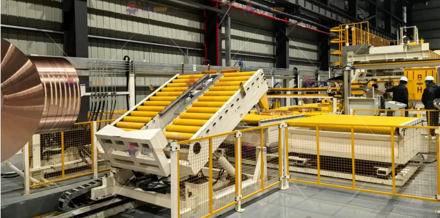
Assembly is the phase where individual modules, custom-machined parts, and standard components converge into a fully operational system. In the case of a modern coil packing line, these modules often include:
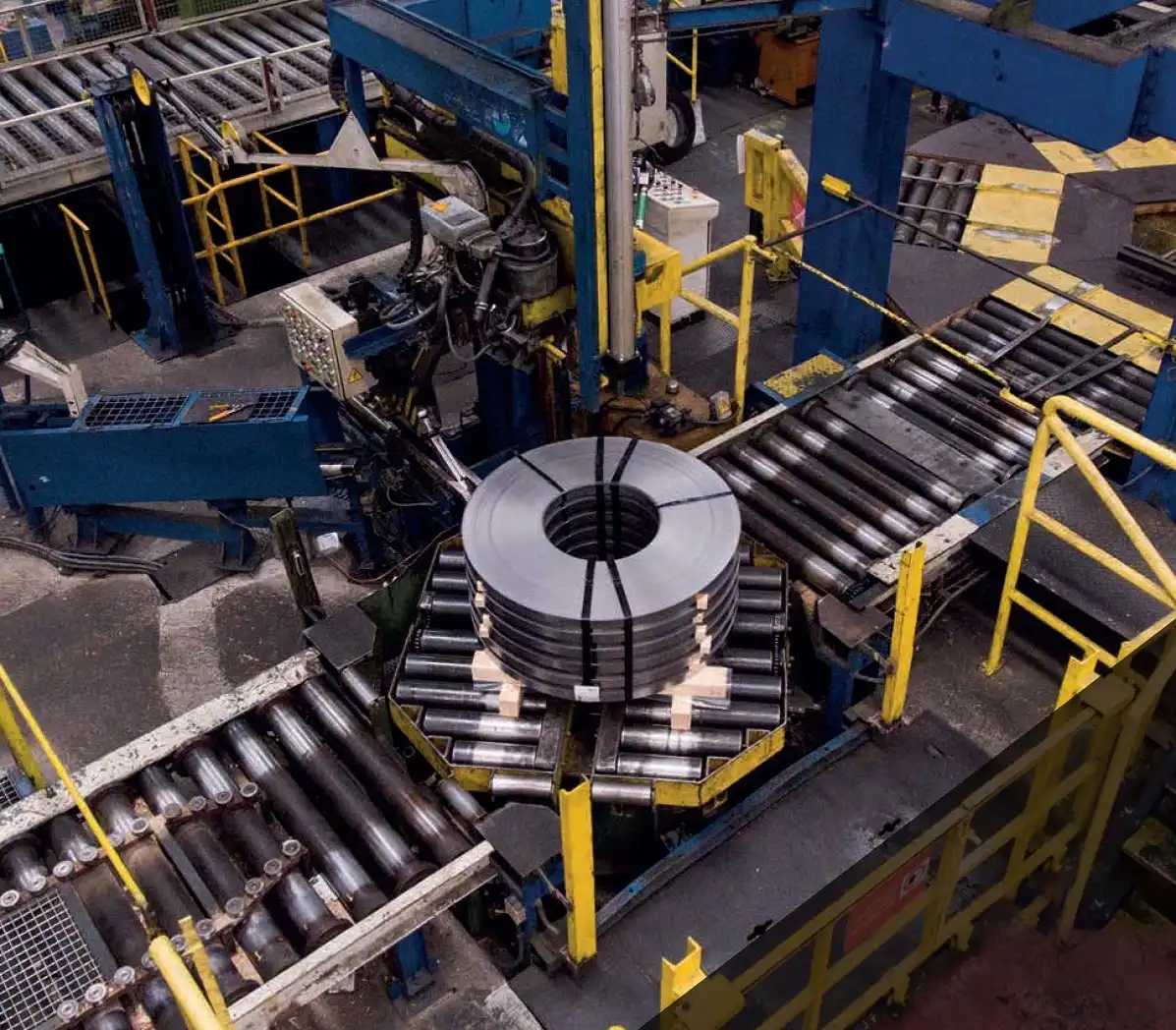
Coil Conveyance Modules
- Motorized rollers, guiding rails, or turnstiles to position the coil.
- Support structures made of high-strength steel to bear the weight of coils.
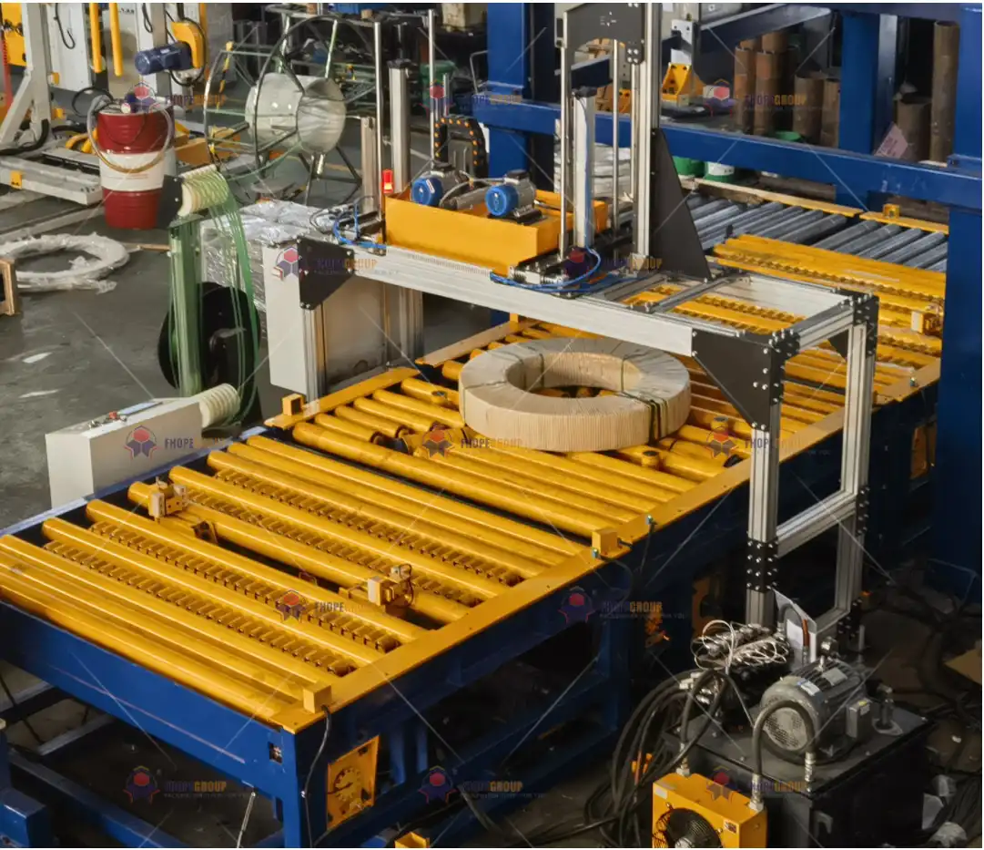
Strapping and Wrapping Units
- Electric and pneumatic strapping heads for tension control.
- Stretch film units or wrapping arms driven by servo motors to achieve consistent overlay.
Hydraulic Actuation Systems
- Cylinders for vertical and horizontal clamping.
- Hydraulic power packs designed to maintain stable pressure and flow rates.
Electrical Drives and Control Cabinets
- PLCs for integrated logic control.
- VFDs for motor speed management.
- Servo drives for high-precision motion.
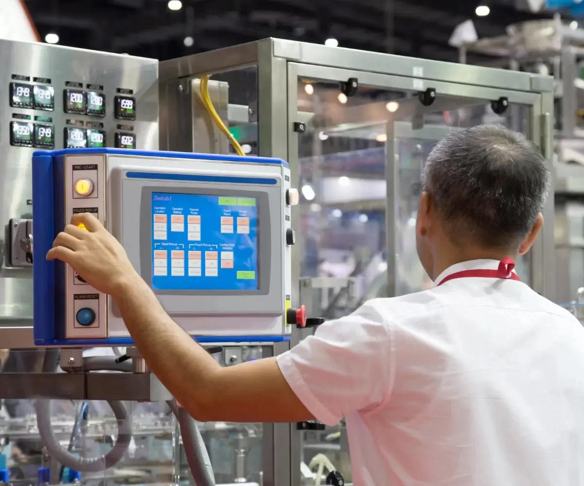
- HMIs (Human-Machine Interfaces) for operator input and monitoring.
Safety and Protective Mechanisms
- Light curtains, emergency stops, and safety relays.
- Mechanical guards and covers for rotating elements.
During assembly, these components are meticulously positioned and secured according to the design documentation, ensuring that mechanical tolerances, load distribution, and alignment criteria are strictly maintained. A thorough check of all connections—be they electrical terminals, hydraulic couplings, or mechanical fasteners—safeguards system integrity.
3. Mechanical Design Norms and Pre-Assembly Considerations
3.1 Structural and Material Selection
From the standpoint of structural reliability, a coil packing line must withstand dynamic loads caused by coil transfer, lifting, and strapping operations. Therefore, materials are selected based on fatigue strength and corrosion resistance. Common criteria include:
- High-Strength Alloy Steel (e.g., 42CrMo) for gear shafts, coupling, and load-bearing frames.
- Wear-Resistant Polymers (e.g., polyurethane or reinforced composites) for guide rollers and contact points.
- Galvanized or Aluzinc Steel Sheets (meeting EN 10346) for outer panels and protective covers to resist corrosion in high-humidity or corrosive environments.
Moreover, engineering teams conduct Failure Modes and Effects Analysis (FMEA) to identify potential weak points in parts such as hydraulic tubing, servo motor insulation, or gear meshing. This risk-based approach ensures that the chosen materials and design features address the operational hazards from day one.
3.2 Tolerancing and Dimensional Checks
Before any component is assembled, it undergoes rigorous dimensional inspection:
- Shape and Position Tolerances: Typically controlled by GB/T 1184 or equivalent ISO standards. For instance, coaxial alignment of servo drive shafts is held to ±0.02 mm to minimize vibration and noise.
- Surface Finish Requirements: Critical for mating surfaces, ensuring that friction and wear do not exceed design limits.
Where needed, advanced metrology tools—like laser trackers or coordinate measuring machines (CMMs)—verify complex geometry. This ensures that when subcomponents arrive at the assembly station, they meet or exceed the mechanical specifications necessary for high-precision integration.
4. The Core Assembly Workflow
A coil packing line assembly is commonly structured into several key phases:
Base Frame and Primary Structure Setup
- Align and level the main frame using precision leveling devices.
- Confirm flatness and structural rigidity to maintain proper reference points.
Subassembly Mounting
- Install roller tables, tensioning devices, and rotation units, each bolted and locked to pre-drilled holes based on a 3D layout.
- Use torque wrenches to tighten bolts to the specified torque values from the engineering BOM (Bill of Materials).
Hydraulic System Integration
- Mount hydraulic power packs, reservoirs, and piping lines following ISO 4413 guidelines for pressure vessels and hoses.
- Route hoses and pipes with ample bend radii, secure them with clamps, and check for potential abrasion points.
- Perform preliminary pressure tests on each circuit to detect possible leaks or substandard fittings.
Electrical and Control Wiring
- Position PLCs, VFDs, servo drives, and contactors within control enclosures rated to IP54 or higher (IEC 60529).
- Route high- and low-voltage cables in separate cable trays to mitigate electromagnetic interference.
- Terminate control signals at the PLC I/O modules, ensuring shielded cables for encoder feedback from servo motors.
Motion Calibration and Servo Alignment
- Couple servo motors to gearboxes or ball screws (if present) with minimal angular or offset misalignment.
- Conduct calibration routines—often with laser or dial gauge setups—to confirm alignment within ±0.02 mm, minimizing servo stress.
- Utilize manufacturer-recommended tools (e.g., offset alignment brackets) to ensure a robust mechanical fit.
Sub-System Commissioning
- Sequentially power up each module, verifying motor rotation direction, sensor signals, and hydraulic pressures.
- Validate basic HMI controls for manual jogging, emergency stops, and auto-mode transitions.
In-Process Quality Checks (IPQC)
- Inspect critical areas using checklists that address torque values, mechanical clearances, sensor bracket positioning, oil line routing, etc.
- Tag any assembly discrepancies for immediate rework. This might involve re-shimming a motor base or repositioning an optical sensor bracket.
5. Hydraulic and Electrical Interplay
5.1 Hydraulic System Requirements
In a coil packing line, the hydraulic system is critical for delivering the force needed to clamp and lift heavy coils. Key concerns include:
- Pressure Stability: The system must maintain pressure fluctuations within ±1.5% of the setpoint to ensure consistent clamping forces.
- Contamination Control: Oil cleanliness is monitored through ISO 4406 or NAS 1638 standards. A typical requirement might be NAS 1638 Class 6 to protect sensitive servo valves or proportional valves.
To reduce cycle time, the hydraulic system may incorporate accumulators that store energy and provide instantaneous flow. All fittings, seals, and hoses typically follow SAE or DIN standards, ensuring they can handle the temperature, pressure, and vibration in harsh industrial settings.
5.2 Electrical Control Precision
Where hydraulic systems provide the raw force, electrical controls offer the precision. Modern coil packing lines rely heavily on:
PLC Control
- Manages interlocks between various stations (pack, strap, stack).
- Monitors sensor feedback (proximity switches, photo-eyes, load cells) to orchestrate fully automated workflows.
- Implements safety logic (e-stops, gates, and alarms).
Variable Frequency Drives (VFDs)
- Control the speed of induction motors driving conveyors or rotating heads.
- Optimize energy consumption by adjusting the motor’s operating speed to match process demands.
Servo Drives and Motors
- Provide precise motion for wrapping arms, strapping heads, or coil positioning.
- Achieve sub-millimeter accuracy and repeatability for tasks such as film tensioning.
During assembly, technicians meticulously check cable routing and grounding practices to minimize electrical noise, especially for servo systems that demand clean encoder signals to maintain accurate control loops.
6. Testing and Commissioning Protocol
Once mechanical, hydraulic, and electrical assemblies are complete, the system enters a rigorous testing phase before shipment or on-site installation:
No-Load Testing
- Verifies the free movement of all components—rollers, clamps, rotating arms—without introducing the actual coil.
- Tests for possible collisions, abnormal vibrations, or uncalibrated sensor positions.
Functional Subsystem Tests
- Servo System: Check homing sequences, jog at various speeds, confirm positioning accuracy with a dial indicator or laser measure.
- Hydraulic System: Cycle clamps and lifts under low pressure first, then proceed to nominal operating pressure. Observe for leaks or pressure drop.
- Safety Systems: Validate e-stop functionality, check photo-eyes and light curtains, confirm the PLC transitions the system into a safe state immediately upon fault detection.
Load Testing
- Introduce real or simulated coils (via weight blocks or dummies) to replicate operating conditions.
- Monitor torque, motor current, and oil temperature over extended cycles to ensure the design can handle normal production demands.
Cycle Time and Output Verification
- Record cycle times for each packing operation. For example, a packaging line might be designed to handle up to 60 coils per hour.
- Verify that the system can meet or exceed customer throughput requirements without compromising safety or product quality.
Final Acceptance Tests (FAT)
- Conduct a comprehensive trial witnessed by the client or certification bodies.
- Provide documented proof of compliance—machine capability charts, SPC (Statistical Process Control) data, and test reports that confirm functional readiness.
7. Quality Control and Documentation
7.1 Quality Control Checkpoints
Throughout assembly and commissioning, certain checkpoints anchor the quality management plan:
Dimensional Inspections
- Performed at pre-assembly and post-assembly to confirm minimal deviations.
- Typical acceptance criteria: ±0.1 mm/m planarity, ±0.2° angular alignment for brackets.
Mechanical Fastening Verification
- Torque checks using calibrated tools, referencing values from design specifications.
Hydraulic Leak Tests
- Pressurize lines to 1.25–1.5 times the normal operating pressure, maintaining the set point for a specified duration while inspecting all joints.
Electrical Continuity and Insulation Tests
- Use megohmmeters to ensure insulation resistance meets or exceeds mandated thresholds (often >1 MΩ at 500 Vdc).
- Confirm correct grounding to prevent static buildup or shock hazards.
Software Integrity
- Secure version control for PLC and HMI programs, validated per IEC 61131-3 standards.
- Backup logic to offline repositories for traceability.
7.2 Documentation and Traceability
All assembly, testing, and inspection data is documented to provide a comprehensive equipment history. Modern companies often rely on Product Lifecycle Management (PLM) software (e.g., Siemens Teamcenter or PTC Windchill) to maintain revision histories, CAD data, and test results. This ensures:
- Traceability: Each coil packing line can be tracked by serial number and build date, linking it to the exact configuration of drives, motors, and hydraulic units.
- Warranty & Maintenance: Operators can reference original assembly records to expedite part replacements or upgrades.
- Continuous Improvement: Feedback from field service is integrated into future design iterations.

8. Emphasis on Safety and Compliance
Beyond productivity and mechanical performance, safety ranks as a paramount concern. The coil packing line must comply with various standards, such as EN 415-8 (safety of packaging machinery) and ISO 12100 (machinery safety—basic concepts and general principles).
Risk Assessments
- Conducted during early design phases to identify pinch points, crush zones, or ejection hazards.
- Mitigated through physical guarding, interlocked access doors, safety PLC logic, and fail-safe sensors.
Operator Training
- Provides instruction on startup/shutdown sequences, emergency procedures, and basic troubleshooting.
- Focuses on correct coil loading/unloading to prevent injuries from falling or rolling coils.
Maintenance Guidelines
- Encourages lockout-tagout (LOTO) protocols.
- Outlines intervals for hydraulic fluid testing, motor belt tension checks, and PLC diagnostic reviews.
9. Lifetime Support and Predictive Maintenance
9.1 Long-Term Reliability
Achieving a high Mean Time Between Failures (MTBF) is crucial for ensuring minimal downtime in demanding production schedules. Design strategies to reach MTBF ≥ 10,000 hours often include:
- Robust Component Selection: Motors and servos from reputable brands tested to industrial-grade reliability.
- Redundant System Architectures: Key modules like power supplies or sensor systems incorporate redundancy or quick-swap capabilities.
9.2 Predictive Maintenance and IoT Integration
With the advent of Industry 4.0 practices, many coil packing lines now feature real-time condition monitoring:
- Vibration Sensors: Track bearing health in motors, gearboxes, or tension rollers. Anomalies in vibration spectra can forewarn mechanical failures.
- Oil Contamination Sensors: Evaluate cleanliness levels in real time, triggering filter replacement before sludge accumulation damages valves.
- Data Analytics: PLC or industrial PC logs operational data (cycle counts, error codes, motor currents). Analyzed through specialized software (e.g., Beckhoff TwinCAT or Rockwell Historian) for predictive insights.
10. Concluding Remarks
The assembly process for a coil packing line merges mechanical engineering, hydraulic design, electrical integration, and advanced control systems into a cohesive, high-performing installation. Each sub-step—whether aligning a servo drive or sealing a hydraulic junction—demands rigorous adherence to design norms, dimensional tolerances, and quality checks. As we integrate cutting-edge PLC logic, servo motors, and real-time diagnostics, the line evolves into a future-proof solution capable of adapting to fluctuating production requirements.
Key Takeaways:
- Holistic Engineering: Material selection, structural integrity, and robust engineering workflows underpin reliability.
- Precision Assembly: Detailed attention to alignment, torque, and calibration ensures smooth operation and extended service life.
- Safety and Compliance: Conformance to international codes (ISO, EN, GB/T) provides a solid framework for hazard prevention.
- Lifecycle Support: From design verification to predictive maintenance, the assembly process sets the foundation for a low-risk, highly efficient operational lifecycle.
By following these best practices and adopting a quality-first approach, fabricators and end-users alike can realize the full benefits of a well-assembled, high-throughput coil packing line. The result is a system that not only meets performance metrics but also offers robust safety features, simplified maintenance, and traceable documentation—critical facets in today’s competitive metal-processing marketplace.
Final Note:
This production procedure for assembling a coil packing line is intended to serve as a customer-facing technical orientation. Specific values, standards, and methods may be adjusted based on local regulations, client requirements, and ongoing technological advances. Always consult the project’s engineering documentation and certified drawings for the latest, most accurate directives.