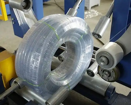
When it comes to manufacturing efficiency, ensuring that every component of the production line communicates seamlessly is crucial. Connecting an inject printer with a cable coiling and strapping machine for marked point cutting requires precision, proper configuration, and an understanding of both equipment specifications and operational needs. This integration isn’t just about hardware; it’s about optimizing workflows and achieving consistent results.
Efforts to connect these devices often bring up challenges such as signal compatibility, software alignment, and timing synchronization. Yet, once set up correctly, the rewards are undeniable: reduced errors, streamlined processes, and enhanced output quality. Let’s dive into how this can be achieved step by step.
From understanding the role of marked point cutting to establishing proper connectivity protocols, this guide will equip you with the knowledge to bridge the gap between your inject printer and cable coiling machine effectively. By the end, you’ll have actionable insights to ensure your production line runs like clockwork.
[Claim] Proper integration of an inject printer with a cable coiling and strapping machine can significantly enhance operational accuracy and productivity, provided the right configuration steps are followed.
1. Why is seamless integration essential for marked point cutting?
1.1 Understanding marked point cutting and its importance
Marked point cutting refers to the precision-driven process where markings are made on cables, indicating exact locations for cutting or further processing. These markings ensure the product meets strict manufacturing specifications, reducing waste and increasing quality control. When an inject printer communicates effectively with the cable coiling and strapping machine, these markings align perfectly with the cutting points.
The lack of integration can lead to misaligned cuts, wasted materials, and decreased production efficiency. Seamless integration allows the machinery to work in harmony, delivering consistent and accurate results that meet production standards.
1.2 Key components for integration: Breaking down the essentials
To connect an inject printer to a cable coiling and strapping machine, you’ll need to consider several key components:
| Component | Function |
|---|---|
| Signal Converters | Convert printer outputs to machine inputs |
| Control Modules | Synchronize timing between devices |
| Communication Protocols | Ensure compatibility between systems |
In most cases, integrating these devices requires configuring the inject printer to output signals in formats the coiling machine can interpret. Common protocols include RS232 or Ethernet, depending on the machinery specifications.
1.3 Steps to configure inject printer for signal output
Configuring the inject printer involves accessing its settings and aligning its output signals with the receiving machine. Typically, this includes:
- Selecting the right signal type (e.g., pulse or NO/NC contact).
- Adjusting timing parameters to match the machine’s operating cycle.
- Testing signal strength and frequency for reliability.
By ensuring these configurations are in place, the inject printer will consistently mark the correct points on the cable.
1.4 The role of timing synchronization in integration
Timing synchronization ensures that the printer and the coiling machine act simultaneously. Misalignment, even by milliseconds, can cause marked points to miss their intended cutting locations. Synchronization relies on real-time signal feedback, often managed through programmable logic controllers (PLCs).
For example, if the machine operates at 60 cycles per minute and the printer delivers signals at 62 cycles, miscommunication will occur. Matching these cycles avoids such errors and ensures operational harmony.
1.5 True or False: Two key facts about marked point integration
True: A programmable logic controller (PLC) can ensure accurate timing between devices by processing input signals and triggering actions in real-time.
False: All inject printers and cable coiling machines are universally compatible and do not require additional converters or protocols for integration.
Proper integration is a tailored process that depends on the specifications of the devices involved.
2. What are the key components needed for the connection?
2.1 The building blocks of integration
To achieve seamless communication between an inject printer and a cable coiling and strapping machine, understanding the components involved is essential. Each piece plays a critical role in ensuring signal accuracy, timing, and functional compatibility. Without these, the integration risks delays or errors in marked point cutting.
The foundation of a successful connection starts with proper cabling, followed by compatible signal transmission devices. Whether you’re using pulse signals, relay outputs, or programmable logic controllers (PLCs), selecting the right components ensures uninterrupted data flow.
2.2 Breaking down the connection: Essential components and their roles
| Component | Role |
|---|---|
| Inject Printer | Marks the precise cutting points on cables. |
| Cable Coiling Machine | Receives the marked cables for cutting and coiling. |
| Signal Converter | Translates the printer’s output into readable machine signals. |
| Relay Module | Provides electrical isolation and prevents signal interference. |
| PLC | Synchronizes the timing and sequence of operations. |
These components ensure the flow of data and commands from the printer to the coiling machine without interruption. Below is a simplified table for quick visualization:
| Device | Signal Type | Compatibility |
|---|---|---|
| Inject Printer | Pulse Signal | RS232/Ethernet |
| Coiling Machine | NC/NO Contacts | RS485/Ethernet |
The integration often requires additional setup, such as configuring protocols or adjusting the PLC’s response time.
2.3 Signal flow and the synchronization process
Signal synchronization ensures that the inject printer and the coiling machine communicate effectively. The process involves:
- Input Signal Calibration: The inject printer sends a pulse signal when marking a cable.
- PLC Control Logic: The PLC interprets this signal and triggers the coiling machine.
- Output Response Adjustment: Feedback from the coiling machine confirms the action, preventing misalignments.
Below is a typical synchronization cycle:
| Step | Action |
|---|---|
| Marking initiation | Inject printer places a mark on the cable. |
| Signal relay | PLC transmits timing data to the machine. |
| Cutting and coiling | Machine cuts and coils at the marked point. |
| Feedback to printer | Machine confirms action to the printer. |
This loop repeats continuously, ensuring marked point cutting accuracy.
2.4 Dive deeper: Cable connection best practices
Connecting devices involves more than plugging in cables; it’s about ensuring signal reliability. Follow these best practices:
- Use shielded cables to minimize electromagnetic interference (EMI) between the printer and machine.
- Match signal types (e.g., digital or analog) for compatibility.
- Test cable length limits to avoid signal degradation.
Here’s a checklist for successful cable connections:
| Checklist Item | Status |
|---|---|
| Shielded cables installed | ✅ |
| Correct signal type selected | ✅ |
| PLC configured for real-time sync | ✅ |
Failing to adhere to these can lead to data loss or delayed commands.
2.5 True or False: Facts about signal flow
True: Using shielded cables reduces electromagnetic interference and improves signal reliability in noisy industrial environments.
False: Once installed, signal synchronization does not require any ongoing adjustments.
Signal synchronization often needs periodic calibration to account for changes in operational speed or machine wear and tear.
3. How can signal synchronization be achieved effectively?
3.1 Why is synchronization critical in marked point cutting?
In any automated system, timing is everything. Signal synchronization ensures the inject printer’s marking aligns perfectly with the cable coiling and strapping machine’s operations. Without proper synchronization, even a millisecond delay can result in misaligned cuts, wasted materials, and production downtime.
Achieving synchronization requires a deep understanding of machine cycles, signal latency, and real-time control systems. With the right tools, synchronization enhances precision, boosts productivity, and ensures consistent quality in marked point cutting.
3.2 Tools and techniques for synchronization
Proper synchronization depends on the interplay of hardware, software, and control mechanisms. Below are the tools and techniques used for effective synchronization:
| Tool/Technique | Purpose |
|---|---|
| Programmable Logic Controller (PLC) | Manages timing and signal flow. |
| Encoder | Tracks machine position for precise timing. |
| Signal Filters | Reduces noise and ensures clear communication. |
| Adjustable Timing Settings | Fine-tunes signal delays for accuracy. |
To understand the process better, here’s a table illustrating typical signal timings:
| Device | Signal Delay (ms) | Response Time (ms) |
|---|---|---|
| Inject Printer | 2-5 | 10 |
| Coiling Machine | 5-8 | 15 |
| PLC | 1-2 | 3 |
By managing these timings, the system ensures harmony between devices, even at high production speeds.
3.3 Advanced synchronization methods
For more complex setups, advanced synchronization techniques are necessary:
- Encoder Integration: Using encoders to monitor cable length and provide real-time feedback to the PLC. This ensures the inject printer marks the cable at the correct position relative to the coiling machine’s operation.
- Cycle-Based Timing: Aligning the printer’s output signals with the machine’s production cycles, ensuring consistency even during variable speeds.
- Real-Time Monitoring Systems: Using industrial monitoring software to track signal flow and detect delays or errors instantly.
These advanced methods are particularly useful in high-volume production environments.
3.4 Troubleshooting synchronization challenges
Even with the best setup, synchronization issues can arise. Below are common problems and solutions:
| Challenge | Solution |
|---|---|
| Signal delays | Check for EMI interference and use signal boosters. |
| Misaligned cutting points | Recalibrate the encoder and adjust timing settings. |
| Inconsistent performance | Update the PLC firmware and test with dummy loads. |
Ensuring each component operates within its design specifications minimizes these challenges and keeps production on track.
3.5 True or False: Facts about synchronization
True: Encoders play a crucial role in synchronization by providing real-time positional feedback to ensure precise marking and cutting.
False: Once synchronization is set, it remains consistent without further adjustments, even as machine speed changes.
Synchronization requires ongoing monitoring and occasional recalibration to adapt to production variability and equipment wear.

4. What challenges arise during integration, and how can they be solved?
4.1 The complexity of integrating diverse equipment
When connecting an inject printer with a cable coiling and strapping machine, challenges often arise due to differences in hardware, communication protocols, and operational timing. Each piece of equipment may have unique specifications, which can lead to compatibility issues if not addressed properly.
The most common integration difficulties include mismatched signal types, timing misalignments, and insufficient feedback loops. Addressing these challenges requires a proactive approach that combines technical expertise with the right tools.
4.2 Common integration challenges and their solutions
Below are some typical issues encountered during integration and the steps to resolve them:
| Challenge | Solution |
|---|---|
| Signal type incompatibility | Use a signal converter to align the printer’s output with the machine’s input. |
| Timing synchronization errors | Implement a PLC to manage timing and resolve delays. |
| Communication protocol mismatch | Ensure both devices support a common protocol, such as RS232 or Ethernet. |
| Feedback loop interruptions | Use real-time monitoring systems to detect and resolve feedback issues. |
Data Overview Table
| Challenge | Frequency (%) | Impact on Operations |
|---|---|---|
| Signal Incompatibility | 35 | Medium |
| Timing Errors | 25 | High |
| Protocol Mismatch | 20 | Medium |
| Feedback Interruptions | 20 | High |
4.3 How to prevent integration issues from recurring
The key to avoiding recurring integration problems lies in proactive planning and continuous monitoring. Consider these best practices:
- Standardized Equipment: Invest in devices that adhere to industry standards for communication and signal output.
- Routine Calibration: Periodically check and adjust synchronization parameters to maintain alignment.
- Documentation and Training: Ensure operators are well-trained and have access to detailed manuals for troubleshooting.
By implementing these measures, you can build a system that is both reliable and adaptable.
4.4 Dive deeper: Enhancing long-term integration success
Long-term success in integration requires more than just solving immediate problems. It involves:
- Upgrading Technology: As newer devices are introduced, upgrading older equipment ensures compatibility and efficiency.
- Developing Redundant Systems: Redundancy in signal pathways and feedback loops prevents single points of failure.
- Utilizing Data Analytics: Leveraging production data helps identify patterns and potential issues before they escalate.
Here’s a checklist for ensuring long-term success:
| Action | Frequency | Impact |
|---|---|---|
| Routine Calibration | Monthly | Prevents timing misalignments. |
| System Upgrades | Annually | Enhances compatibility. |
| Data Analytics Review | Weekly | Identifies inefficiencies. |
4.5 True or False: Facts about integration challenges
True: A programmable logic controller (PLC) is often essential for resolving timing synchronization issues between an inject printer and a cable coiling machine.
False: Signal converters are optional for integration, as most devices are inherently compatible without additional equipment.
Signal converters are frequently necessary to bridge the gap between incompatible devices, ensuring smooth communication across the production line.

Conclusion
Integrating an inject printer with a cable coiling and strapping machine for marked point cutting can transform production lines by improving accuracy, reducing waste, and enhancing overall efficiency. This process, while complex, is achievable with the right tools, methods, and understanding of the systems involved.
Ensuring compatibility between devices, calibrating timing, and establishing reliable signal pathways are the pillars of a successful connection. Ongoing monitoring and preventive maintenance further guarantee long-term stability and performance. As manufacturing demands continue to evolve, investing in seamless integration and continuous optimization becomes not just a necessity but a competitive advantage.
[Claim] Proper integration and consistent maintenance ensure that an inject printer and cable coiling machine work harmoniously, delivering unmatched precision and reliability in marked point cutting processes.
Get Your Best Solution !
